
Understanding SCG Failure in 5G Dual Connectivity: Causes, Procedures, and Recovery Mechanisms

Understanding SCG Failure in 5G Dual Connectivity
As 5G networks keep evolving, Dual Connectivity (DC) has emerged as a key technology for smooth transitions between LTE (4G) and NR (5G) layers. In this mixed setup, user devices can connect to both an LTE eNodeB (eNB) and a 5G gNodeB (gNB) at the same time, which helps in providing higher speeds and better coverage.
That said, this complex system does bring along new challenges when it comes to maintaining stable connections—one of the biggest being SCG (Secondary Cell Group) Failure.
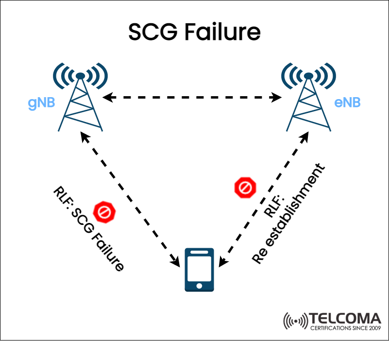
The diagram we've uploaded gives a visual look at this scenario. It illustrates how a Radio Link Failure (RLF) between the User Equipment (UE) and the gNB leads to SCG Failure, followed by recovery through the main LTE eNB.
What is SCG Failure in 5G Dual Connectivity?
In 5G Dual Connectivity, the UE (User Equipment) keeps two radio connections alive simultaneously:
Primary Cell Group (PCG) – Managed by the Master Node (MN), typically the eNB in LTE.
Secondary Cell Group (SCG) – Managed by the Secondary Node (SN), normally the gNB in 5G NR.
These connections team up to improve data rates, cut down on latency, and enhance overall user experience.
An SCG Failure kicks in when the radio link between the UE and the gNB (Secondary Node) drops, while the primary LTE connection stays active.
This kind of failure gets flagged as a Radio Link Failure (RLF) in the SCG, prompting the UE to start a recovery process.
Understanding the Image: How SCG Failure Happens
The diagram clearly outlines the signaling relationships and where failures can occur:
The gNB stands for the 5G NR base station (Secondary Node).
The eNB is the LTE base station (Master Node).
The UE (User Equipment) connects to both.
When the SCG link (UE ↔ gNB) suffers from poor signal quality, packet loss, or a disruption, the UE reports an SCG Failure. The Master Node (eNB) steps in to ensure the connection doesn’t completely drop.
In the image:
The RLF: SCG Failure arrow illustrates the loss of link between the UE and gNB.
The RLF: Re-establishment arrow shows recovery through the LTE eNB connection.
This design guarantees service continuity even if 5G coverage wavers or temporarily fails.
Causes of SCG Failure
There are a number of technical and environmental reasons that can lead to SCG Failures. Here are some of the most frequent culprits:
Radio Link Degradation
Poor signal quality (low SINR or RSRP) between UE and gNB.
Interference from nearby cells or overlapping frequencies.
Mobility-Related Issues
Fast-moving UEs (like vehicles) moving out of the gNB coverage area.
Delays in handover processes between nodes.
gNB Unavailability
The Secondary Node might become temporarily overloaded or unavailable.
There could be software or hardware problems in the 5G cell.
Configuration or Timing Mismatch
Improper synchronization between eNB and gNB.
Delays in X2/Xn interface communications between nodes.
Core Network Delays
Network backhaul congestion causing signaling delays.
Failures in the S1-U or NG-U interface affecting data transfer.
SCG Failure Detection Mechanism
Detecting SCG Failure depends on radio link monitoring (RLM) procedures in both the UE and gNB.
UE Monitoring Process
The UE keeps an eye on:
Reference Signal Received Power (RSRP)
Reference Signal Received Quality (RSRQ)
Signal-to-Interference-plus-Noise Ratio (SINR)
If these metrics drop below a certain threshold for a while, the UE signals RLF (Radio Link Failure) in the SCG.
Reporting the Failure
After detecting RLF:
The UE sends an SCG Failure Information message to the Master Node (eNB).
This message contains failure cause, timestamp, and measured parameters.
Master Node Decision
Once the eNB (Master Node) gets the report, it decides:
Whether to re-establish the SCG with the same gNB.
Or to initiate a Secondary Node change (i.e., switch to a different gNB).
SCG Failure Recovery Procedures
When an SCG failure happens, the Dual Connectivity architecture ensures that the session stays active through LTE fallback.
RLF Re-establishment
The UE kicks off a Radio Resource Control (RRC) Re-establishment process through the eNB (the Master Node). This is what’s shown in the image as “RLF: Re-establishment”.
Steps include:
The UE sends an RRC Re-establishment Request to the eNB.
The eNB verifies the UE’s identity and session.
If everything checks out, the eNB reconfigures resources and reconnects.
Secondary Node Reconfiguration
After re-establishing:
The eNB might initiate a Secondary Node Addition process.
A new gNB (or the same one if it’s back) gets added via the X2 or Xn interface.
The UE seamlessly resumes dual connectivity.
Service Continuity
Throughout this process:
The LTE connection keeps control plane signaling active.
Data transfer might temporarily run on LTE only, but there’s no session drop.
Once SCG recovery is done, dual connectivity goes back to normal.
RRC Messages Involved in SCG Failure Handling
Stage Message Type Function
Detection RLF Indication UE spots SCG link loss and prepares to notify eNB
Reporting SCG Failure Info UE sends failure info to eNB
Re-establishment RRC Reestablishment Request UE works to re-establish the LTE control link
Recovery RRC Reconfiguration eNB adds or reconfigures the gNB connection
These signaling messages standardize failure detection and recovery across all 3GPP-compliant 5G networks.
Key Performance Metrics in SCG Failure
Keeping an eye on SCG failures is super important for optimizing the network. Common KPIs include:
SCG Failure Rate (%): The ratio of SCG failures against total dual connections.
RLF Recovery Time (ms): The time needed to re-establish the connection.
Success Rate of SCG Reconfiguration: How often re-adding a connection succeeds.
Secondary Node Change Count: The frequency of SN changes due to instability.
Throughput Drop Duration: The period when the UE operates only in LTE mode.
Operators rely on these metrics for SON (Self-Organizing Network) optimization and handover tuning.
How Operators Minimize SCG Failures
Telecom engineers use several approaches to lower SCG failure rates:
Optimizing Xn/X2 Interface Latency
Ensures quick coordination between eNB and gNB.
Deploys fiber or high-capacity microwave backhaul.
Advanced Mobility Algorithms
Predictive mobility and machine learning help choose the best gNB.
Dynamic Thresholds
Adaptive signal thresholds based on traffic and mobility loads.
Power Control & Beamforming
Strengthens signal quality between UE and gNB.
Redundant SCG Paths
Provides quick switching to another gNB if a link is lost.
Continuous KPI Monitoring
Uses analytics to catch early signs of degradation before failure kicks in.
SCG Failure vs. Complete Link Failure
Parameter SCG Failure Full Link Failure
Affected Node Secondary Node (gNB) Both eNB and gNB
Control Plane Remains active via LTE Lost completely
Recovery Trigger RRC Re-establishment via eNB Reconnection from idle state
Service Impact Temporary throughput drop Complete session drop
This distinction is key: SCG failure doesn’t disconnect the user entirely—it just rolls the service back to LTE until the 5G link is back up.
Conclusion
SCG Failure is just part of the dynamic 5G Dual Connectivity environment. It occurs when the secondary 5G link (SCG) drops due to poor signal, mobility, or node issues, but the primary LTE link (PCG) keeps the control plane running.
With tools like RLF detection, RRC re-establishment, and secondary node reconfiguration, modern 5G systems make sure that user experiences remain as uninterrupted as possible.