
Understanding Supplementary Uplink (SUL) in 5G and LTE: Extending Uplink Coverage and Performance

The Explanation of Supplementary Uplink (SUL) in 5G and LTE
As mobile networks develop toward higher speeds and more coverage, Uplink performance continues to be a challenge for engineers, especially on the cell edge. Engineers adopted Supplementary Uplink (SUL) in LTE-Advanced and improved it in 5G New Radio (NR) to sidestep limitations in uplink performance and enhance the user experience.
The uploaded graphic outlines that the SUL operates in much the same way as adding the additional frequency to the main NR frequency band with additional information about coverage zones, uplink and downlink asymmetric balance, and frequency allocation.
What is Supplementary Uplink (SUL)?
Supplementary Uplink (SUL) is an additional frequency band that provides uplink (UL) communication entirely for uplink (UL) transmission along with a frequency band that does uplink and downlink (DL) communication.
In other words:
The main NR frequency band (UL + DL) does all the uplink and downlink communication.
The SUL band band (F2) provides extra uplink capacity, especially when the signal is weak from the main frequency uplink band.
This increases overall uplink coverage, performance, and reliability, especially for users further from the base.
The Necessity of Supplementary Uplink
Today's mobile networks support asymmetric data traffic, meaning that users download significantly more than they upload. However, this creates coverage challenges for uplink link budget (the combination of transmission power and path loss). This problem is exacerbated by the higher frequencies that 5G networks leverage.
Reasons to Deploy Supplementary Uplink
Improves uplink coverage for users at the edge of cells.
Compensates for the uplink path loss associated with the higher frequencies in SUL1 and SUL2 bands.
Enhances network coverage by reducing uplink power requirements for user equipment (UE).
Provides uplink reliability for applications that require consistent uplink performance, such as video conferencing or lighter IoT telemetry.
Many times, you'll see that the uplink drops, but the downlink SCR still shows more than acceptable levels, harming user experience and network efficiency.
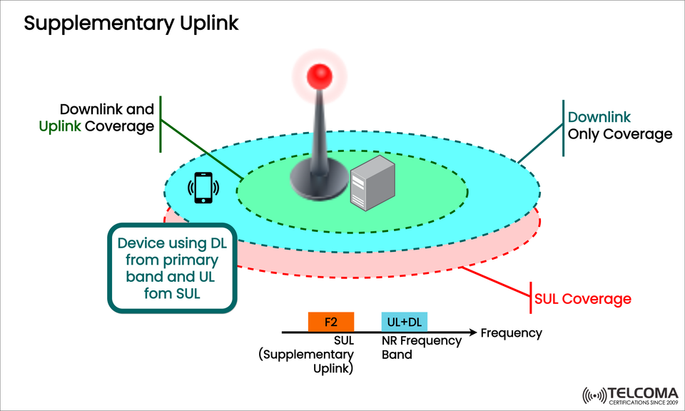
Examining the Diagram
The image that was uploaded also nicely illustrates the functionalities of a Supplementary Uplink Service in a network cell.
Explaining the key aspects of the diagram.
Base Station (gNB/eNB): Base Station(s) are essential to the network cell, as the base station is the node that sends and receives radio signals.
Device (UE): The User Equipment is the device that receives the Downlink (DL) portion of a session from the primary NR frequency band, and uplinked signals (UL) received in the Supplementary Uplink frequency band.
Coverage Areas:
Inner Green Area: This area shows what primary uplink and downlink coverage looks like where both the uplink and downlink function well.
Blue Area: This area indicates downlink-only coverage where the uplink starts to drop due to insufficient power.
Red Area (SUL Coverage): This area represents the area where SUL uplink expands coverage, in which devices can maintain uplink communication with the base station when the main UL fails completely.
Frequency Chart (Bottom)
F2 (SUL Band): This is a supplementary uplink-only frequency which is usually at a lower frequency since lower frequencies provide better propagation.
UL + DL Band: This is the primary NR frequency which provides both uplink and downlink communications.
Together, these coverage areas illustrate how SUL provides uplink communication beyond the coverage limitations of uplink communications.
How Supplementary Uplink Works
Once user equipment (UE) detects the uplink signal is weak on the main frequency band (distance or interference), the UE can switch to the supplementary uplink band to improve the transmission.
Mechanism of Operation
The base station (gNB) will configure the UE with sufficient SUL parameters at the time of connections.
The usage of UEs are:
Primary NR band for UL reception.
Supplemental uplink band (F2) for downlink transmission.
Both frequencies operate simultaneously with carrier aggregation.
This method maintains uplink communications relieved from higher frequency uplink communications that suffer at the cell edge or when going inside the building.
SUL's Technical Characteristics
Parameter Description
Technology 5G NR (also supported in LTE-Advanced)
Operation Type Uplink-only (no downlink)
Frequency Range Typically lower than the primary NR band.
Purpose Improving coverage and reliability for uplink.
Carrier Aggregation Aggregates SUL with the primary carrier.
Propagation Advantages Better propagation due to lower frequency and reduced path loss.
Supplementary Uplink Benefits
Aspect Benefit
Improved Uplink Coverage Allows enhanced uplink reach, especially in rural and cell-edge regions.
Enhanced Uplink Reliability Provides stable uplink connections for UL-centric applications.
Improved User Experience Reduces dropped calls and latency in areas with signal weakness.
Better Utilization of Spectrum Efficient and effective use of low-frequency bands for uplink extension.
Support for Low-Power Devices Serves IoT or battery-constrained devices with limited power budgets.
Supplementary Uplink in LTE vs. 5G NR
The supplementary uplink arose in LTE-Advanced (Release 13), and is now more advanced and strategically significant in 5G NR.
In LTE-A
Use in Carrier Aggregation (CA) cases.
Limited number of uplink-only bands.
In 5G NR
Directly integrated into NR Carrier Aggregation (NR-CA) and Dual Connectivity (DC) structure.
Critical to balancing FR1 (sub-6 GHz) and FR2 (mmWave) frequency combinations.
Obstacles to Implementing SUL
There are several operational and technical challenges involved in deploying SUL, despite its advantages.
Spectrum Availability:
SUL will require low-frequency unpaired or paired spectrum that may be limited or expensive.
Device Compatibility:
Some user equipment (UE) does not support SUL configurations and will need advanced chipsets and firmware.
Configuration Complexity:
A proper configuration will be needed to coordinate where the base station may be transmitting on various carriers in addition to the SUL frequency to avoid or minimize RF interference.
Power Control Optimization:
The network needs to actively control uplink power for efficiency and to minimize interference.
Backhaul and Core Integration:
Bandwidth for aggregated uplink and downlink streams will need to provide an efficient synchronization point across the core.
Example Frequency Configuration
Parameter Primary Band (NR) Supplementary Uplink (SUL)
Frequency Range 3500 MHz (n78) 700 MHz (n28)
Link Type UL + DL UL Only
Coverage Area Moderate Extended (Penetration Better)
Purpose Main communication Extended uplink reach
As an example, this configuration shows the pairing of a low-frequency SUL band with a high-frequency NR band to enhance coverage and capacity.
Future of the Supplementary Uplink in 5G and Beyond
As the 5G network progresses, SUL will be able to mature with support for:
AI-based dynamic uplink based on live conditions of the radio.
Dynamic spectrum sharing for SUL and other bands.
Carrier aggregation across FR1 and FR2 bands for uplink-hybrid flexibility.