
Understanding Telco VNFs: How Virtual Network Functions Use VM Clusters for IMS and Core Network Efficiency

Understanding Telco VNFs: How Virtual Machine Clusters Enable Multi-Function Telecom Systems
Telecom networks are quickly shifting towards virtualized and cloud-native infrastructures. One of the key changes is moving from physical hardware to Virtual Network Functions (VNFs), which is a big part of this transformation.
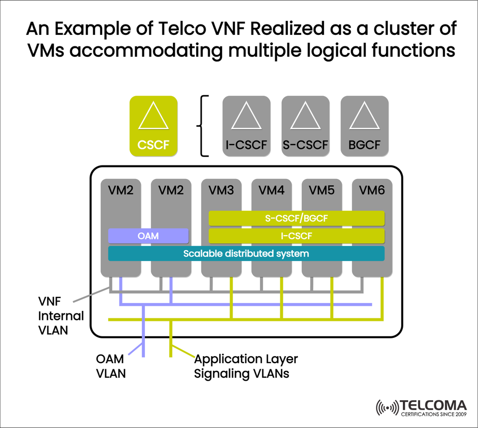
The diagram provided — “An Example of Telco VNF Realized as a Cluster of VMs Accommodating Multiple Logical Functions” — really shows how telecom functions like CSCF, BGCF, and I-CSCF can operate within a cluster of Virtual Machines (VMs).
This shift in architecture allows telecom operators to deploy, scale, and manage complex core network functions more efficiently than ever.
What Is a Telco VNF?
A Virtual Network Function (VNF) is basically a software version of a network function that traditionally needed dedicated hardware.
VNFs are the backbone of Network Function Virtualization (NFV) — a concept put forth by ETSI (European Telecommunications Standards Institute) to transform how telecom networks are structured.
Traditional vs. Virtualized Functions
Traditional (PNF)Virtualized (VNF)Hardware-dependent Software-based Fixed capacity Elastic and scalable Long provisioning times Rapid deployment Manual configuration Automated via NFV MANO High Cap Ex Reduced Cap Ex and Op Ex
In the context of the diagram, VNFs run logical IMS functions like:
CSCF (Call Session Control Function)
I-CSCF (Interrogating CSCF)
S-CSCF (Serving CSCF)
BGCF (Breakout Gateway Control Function)
Together, these functions manage SIP signaling, routing, and call session control in IP Multimedia Subsystem (IMS) networks.
Understanding the Diagram: A Cluster of VMs Running Multiple Logical Functions
The image shows a Telco VNF set up as a cluster of Virtual Machines (VMs). Each VM takes on part of the overall workload — together, they achieve the complete network function.
At the top, you’ll find logical IMS functions — CSCF, I-CSCF, S-CSCF, and BGCF — laid out across VM2 to VM6, all interconnected through various VLANs (Virtual LANs).
This structure demonstrates how multiple IMS roles can exist within a distributed, scalable VNF environment.
Breakdown of Key Elements in the Diagram
Let’s break down the vital components and their connections, step-by-step.
A. Logical Functions (Top Layer)
The logical network functions shown are:
CSCF (Call Session Control Function): Handles SIP signaling and session control within IMS.
I-CSCF (Interrogating CSCF): Manages incoming SIP messages from other networks and queries the HSS.
S-CSCF (Serving CSCF): Registers subscribers, enforces policies, and routes SIP sessions.
BGCF (Breakout Gateway Control Function): Determines where to route calls going out of the IMS network to PSTN.
The diagram shows that S-CSCF and BGCF can share the same virtual infrastructure (VM4–VM5), while I-CSCF can spread resources across VMs for better scalability.
B. Virtual Machines (VMs)
Each VM (VM2 to VM6) is a separate instance of the VNF running on a hypervisor.
These VMs handle parts of the application logic, allowing the whole VNF to work as a scalable distributed system.
For example:
VM2 includes OAM (Operations, Administration, and Maintenance) and helps with internal orchestration.
VM3–VM6 host instances of S-CSCF/BGCF and I-CSCF spread over different nodes.
Together, they form a multi-instance, fault-tolerant VNF cluster.
C. Scalable Distributed System
At the heart of the diagram is a Scalable Distributed System layer, linking all the VMs.
This layer ensures:
Load balancing: Distributes processing tasks evenly.
Session replication: Keeps active call states synchronized across VMs.
Fault tolerance: If one VM goes down, the others keep managing sessions.
Elastic scaling: More VMs can be added as demand increases.
This distributed setup is key for telecom reliability, hitting the industry's five nines (99.999%) availability goal.
D. VLANs and Networking
The diagram illustrates three VLAN types that connect the VMs and functional layers:
VNF Internal VLAN:
Links all VMs within the VNF.
Manages synchronization, database replication, and signaling exchange.
OAM VLAN:
Dedicated to Operations, Administration, and Maintenance traffic.
Supports remote management, telemetry, and software updates.
Application Layer Signaling VLANs:
Handles SIP signaling and communication with outside IMS or core network elements.
Segregated for security and QoS (Quality of Service).
This approach with multiple VLANs ensures isolation between management, control, and signaling planes — a best practice in telecom network design.
Functional Integration: How the Cluster Works Together
When a subscriber makes a VoLTE or VoWiFi call, here's how this virtualized system works:
SIP Signaling Received: The SIP INVITE message comes through the Application Signaling VLAN, reaching the I-CSCF instance.
HSS Query and Routing: The I-CSCF checks with the Home Subscriber Server (HSS) to find the right S-CSCF for the user.
Session Control: The S-CSCF, operating on VM4–VM5, manages the session setup, call control, and routing.
Breakout Decision: If the call needs to go to PSTN, the BGCF figures out where to send it and routes it appropriately.
OAM Monitoring: Throughout the process, the OAM system (VM2) tracks resource usage, performance, and alarms via the OAM VLAN.
This whole process happens seamlessly across distributed VM instances, keeping communication efficient in real-time.
Advantages of VNF-Based Cluster Architecture
This way of designing virtualized network functions brings several major perks:
A. Scalability
Quickly add or remove VMs as traffic changes.
Horizontal scaling means you can expand capacity without changing hardware.
B. High Availability
Fault tolerance means operations keep going during hardware or VM issues.
The distributed setup supports session failover.
C. Resource Optimization
VNFs efficiently share computing and network resources.
Dynamic workload distribution maximizes how well we use hardware.
D. Simplified Management
Centralized OAM makes software upgrades and configuration easier.
Integrating with NFV MANO frameworks automates lifecycle management.
E. Service Agility
Roll out new features or updates more quickly.
Supports CI/CD pipelines for fast telecom service innovation.
Role in Modern Telecom: From VNF to CNF
While VNFs are just the first step in virtualization, telecom networks are moving further towards Cloud-Native Functions (CNFs).
In CNFs, the same network functions are deployed as microservices in containers managed by Kubernetes, providing:
Finer scalability.
Faster recovery times.
Cloud-agnostic setups.
Even so, VNFs remain essential — especially in hybrid environments where both virtual machines and containers are used together.
The architecture shown in the diagram is still foundational for 4G LTE and early 5G core deployments, linking traditional NFV with next-gen cloud-native networks.
Conclusion
The Telco VNF architecture shown in the diagram captures the essence of telecom network virtualization. By hosting multiple logical IMS functions within a cluster of VMs, operators can achieve scalability, flexibility, and operational efficiency.
Through multi-layer VLANs, distributed systems, and function co-location, VNFs deliver telecom-grade performance while cutting down on hardware reliance.
As networks move towards 5G and beyond, grasping this VNF cluster model is crucial for engineers, architects, and decision-makers steering digital transformation.
Essentially, VNFs are the backbone of modern telecom infrastructure — enabling quicker innovation, improved reliability, and a smoother transition to cloud-native networks.