
Understanding the 5G User Plane Protocol Stack: Architecture, Layers, and Interfaces

Understanding the 5G User Plane Protocol Stack
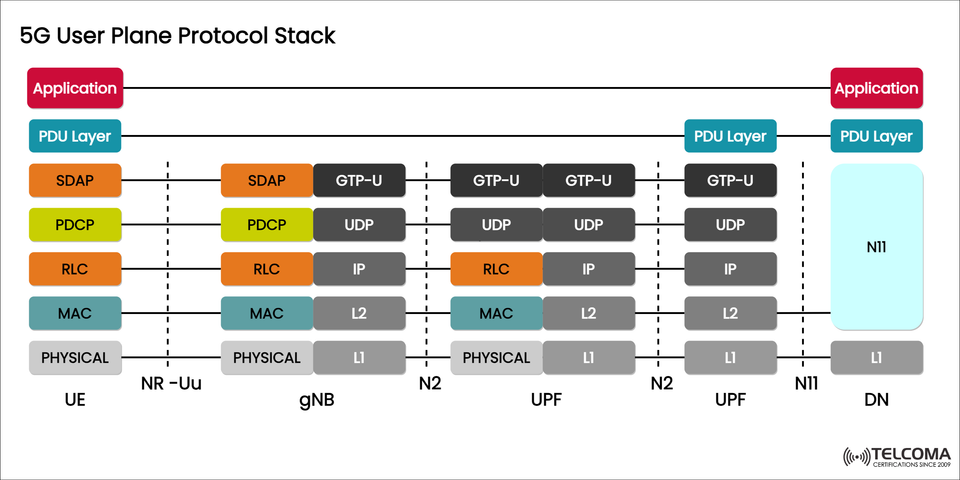
When we talk about 5G technology, the User Plane (U-plane) is crucial for managing user data traffic, which includes everything from video streaming to communications between IoT devices. The diagram uploaded illustrates the 5G User Plane Protocol Stack, showing how user data flows smoothly from the User Equipment (UE) through the gNodeB (gNB) and User Plane Function (UPF) to the Data Network (DN).
This structure is key to achieving ultra-low latency, high throughput, and flexible network slicing in 5G systems.
What’s the 5G User Plane?
The User Plane (U-plane) in 5G is all about transferring user data packets between the UE and the Data Network (DN). This operates alongside the Control Plane (C-plane), which takes care of signaling and session management.
Core Functions of the User Plane:
It efficiently transports user data.
Enforces QoS (Quality of Service).
Routes and forwards traffic.
Handles data encryption and header compression.
Supports seamless mobility across networks and cells.
The User Plane is vital for ensuring that the end-user experience is quick, reliable, and secure.
An Overview of the 5G User Plane Protocol Stack
The 5G User Plane Protocol Stack outlines how user data is processed and sent throughout the network:
Network Entity | Role in User Plane | Example Interface
UE (User Equipment) | Generates and consumes user data. | NR-Uu
gNB (Next Generation NodeB) | Acts as the radio access node; it terminates RLC, PDCP, and SDAP layers. | N3
UPF (User Plane Function) | Routes user packets to and from the data network. | N3, N9
DN (Data Network) | The final destination for user data, like the Internet or an enterprise cloud. | N6
Each of these components has specific protocol layers that work together to manage user data flow.
Layers of the 5G User Plane Stack
The 5G User Plane consists of several protocol layers, each serving a unique purpose. The illustration showcases the interaction between UE, gNB, UPF, and DN.
a. Application Layer
At both ends (UE and DN), the Application Layer consists of user-facing applications—think video streaming, IoT analytics, or voice over IP. This is essentially the service layer relying on the network stack below for data delivery.
b. PDU Layer
The PDU (Protocol Data Unit) Layer is part of the 5G core’s Session Management process. It defines the data structure (like IP or Ethernet PDUs) used for communication between the UE and DN.
It guarantees that each session maintains QoS flow identifiers (QFIs) and Data Radio Bearers (DRBs).
c. SDAP (Service Data Adaptation Protocol)
SDAP is unique to the 5G system (not present in LTE) and handles:
Mapping QoS Flows to Data Radio Bearers (DRBs).
QoS enforcement and differentiation based on service type.
SDAP is found between the PDU Layer and the PDCP in both UE and gNB.
d. PDCP (Packet Data Convergence Protocol)
The PDCP layer ensures data confidentiality, integrity, and header compression.
Key PDCP Functions:
Header compression (ROHC).
Ciphering and deciphering of user data.
Reordering and duplicate detection.
Data integrity protection.
This is where the initial level of encryption and compression takes place, boosting both security and efficiency.
e. RLC (Radio Link Control)
The RLC layer sits between PDCP and MAC, providing error correction and data segmentation.
RLC Modes:
AM (Acknowledged Mode): For reliable data transfer.
UM (Unacknowledged Mode): For real-time services like voice or video.
TM (Transparent Mode): Used for control plane messages.
RLC ensures packets are reassembled and delivered correctly, even if the radio links are unreliable.
f. MAC (Medium Access Control)
The MAC layer oversees radio resource scheduling and the multiplexing of logical channels. It collaborates closely with the Physical (PHY) layer to decide how data is sent over the air.
MAC Functions Include:
Prioritizing traffic based on QoS.
Mapping logical channels to transport channels.
Error detection through Hybrid ARQ.
Efficient uplink and downlink scheduling.
g. Physical Layer (PHY)
The Physical Layer (L1) is responsible for actual radio signal transmission. It encompasses modulation, coding, and antenna mapping techniques like MIMO (Multiple Input Multiple Output) and OFDM (Orthogonal Frequency Division Multiplexing) for high data rates and reliability.
PHY Layer Responsibilities:
Encoding and decoding bits into symbols.
Error correction coding.
Channel estimation and power control.
User Plane Beyond the gNB: GTP-U, UDP, and IP Layers
After user data reaches the gNB, it moves through the N3 and N9 interfaces via the GTP-U (GPRS Tunneling Protocol - User Plane) tunnel towards the UPF.
a. GTP-U (GPRS Tunneling Protocol - User Plane)
Encapsulates user data into GTP-U packets for 5G Core transmission.
Facilitates tunneling between gNB and UPF.
Supports mobility and multi-access edge computing (MEC).
b. UDP (User Datagram Protocol)
Serves as the transport layer for GTP-U packets.
Offers low-latency, connectionless data delivery.
c. IP (Internet Protocol)
Addresses and routes between network functions (gNB, UPF, DN).
Supports both IPv4 and IPv6.
These protocols work together to ensure end-to-end packet delivery within the user plane.
Interfaces in the 5G User Plane
The image highlights several interfaces that are crucial for user plane communication:
Interface | Between | Function
NR-Uu | UE ↔ gNB | Air interface for radio communication.
N3 | gNB ↔ UPF | GTP-U tunnel for user data forwarding.
N9 | Between UPFs | Inter-UPF data forwarding.
N6 | UPF ↔ DN | Connection to external data networks.
These interfaces enable flexible and modular data routing, fostering network slicing and edge computing capabilities.
Data Flow Across the 5G User Plane
Here’s a quick rundown of how a data packet travels through the 5G User Plane:
UE generates a data packet (like an HTTP request).
The packet flows through SDAP → PDCP → RLC → MAC → PHY, reaching the gNB.
The gNB wraps it into GTP-U/UDP/IP and forwards it over the N3 interface to the UPF.
The UPF then sends the packet to the Data Network (DN) via the N6 interface.
The response packet takes the reverse path: DN → UPF → gNB → UE.
This whole process unfolds in milliseconds, delivering the high-speed, low-latency performance that defines 5G.
Advantages of the 5G User Plane Design
The 5G User Plane architecture has numerous benefits over LTE:
Separating user and control planes enhances flexibility.
The QoS-based SDAP layer allows for detailed flow control.
GTP-U tunnels enable efficient multi-access edge computing.
A scalable and virtualized UPF supports cloud-native deployment.
Lower latency and higher throughput thanks to advanced PHY and MAC features.
These improvements make 5G ideal for enhanced mobile broadband (eMBB), massive IoT (mIoT), and ultra-reliable low-latency communications (URLLC).
Conclusion
The 5G User Plane Protocol Stack is fundamental to data transmission in the 5G network. From the SDAP and PDCP layers on the UE to the GTP-U tunneling in the UPF, each layer is crucial for ensuring reliable, secure, and fast communication.
Understanding these layers and interfaces is key for telecom professionals looking to optimize network performance, QoS, and the end-user experience in 5G deployments.
As we look towards 6G, the modular and software-defined nature of the 5G User Plane will continue to serve as a solid foundation for future advancements in global connectivity.