
Understanding the BS Type 1-C Receiver Interface in 5G Base Stations

Understanding the BS Type 1-C Receiver Interface in 5G Base Stations
In the rapidly changing world of 5G and advanced cellular networks, the design of a base station (BS) plays a crucial role in its performance. The BS Type 1-C receiver interface, which has been standardized by 3GPP and industry groups like NGMN, outlines how the base station cabinet connects to various components, including external low-noise amplifiers (LNAs), filters, and antenna systems.
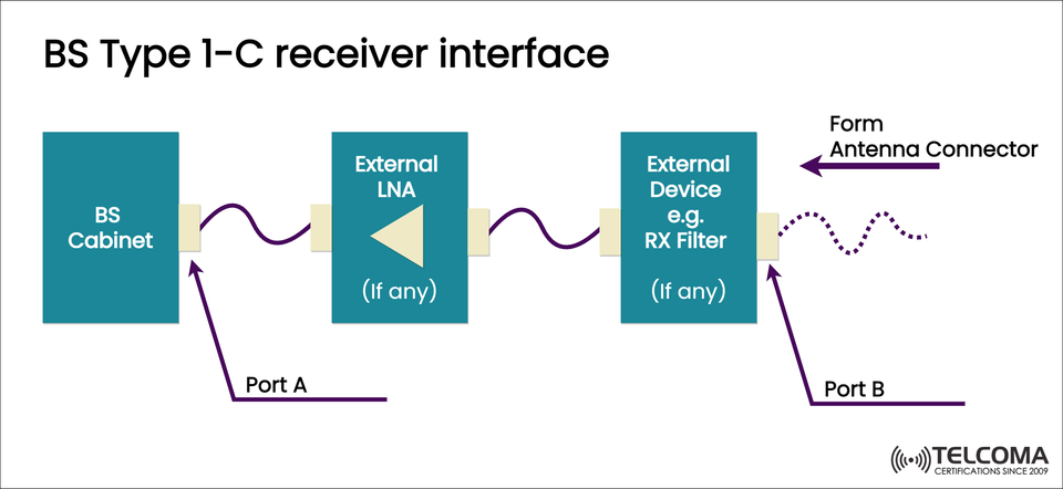
The image above illustrates the signal flow in a Type 1-C setup, showing the path from the base station cabinet to the antenna connector, along with additional components like the external LNA and RX filter.
Let’s take a closer look at how this interface operates, its key components, and why it's essential for enhancing receiver sensitivity and overall network performance.
What Is a BS Type 1-C Receiver Interface?
The BS Type 1-C receiver interface is one of several standardized base station configurations that explain how the radio receiver chain connects to external components.
In a nutshell, it details:
The path and interface connections linking the base station receiver ports (inside the BS cabinet) to the antenna system, which can include optional devices like low-noise amplifiers (LNAs) and receive (RX) filters.
This design choice promotes flexibility, modularity, and optimal noise performance, particularly in networks that use distributed or remote radio head (RRH) architectures.
The Role of the BS Type 1-C Configuration
The Type 1-C setup is all about optimizing receivers in high-performance base stations. Here's what it aims to do:
Lower receiver noise by placing external LNAs close to the antenna.
Filter out unwanted signals before they reach the baseband.
Enhance the signal-to-noise ratio (SNR) for weak received signals.
Accommodate longer feeder cable runs between the antenna and the BS cabinet without losing sensitivity.
You’ll often see this configuration in macro cell sites, remote rural deployments, and high-frequency 5G installations, where keeping the noise figure low is crucial.
BS Type 1-C Receiver Interface Diagram Explained
The provided image clearly depicts the signal chain in a BS Type 1-C receiver setup.
- BS Cabinet
The base station (BS) cabinet contains the radio transceiver modules, baseband units, and processing circuits.
Function: It converts RF signals received from the antenna into baseband signals for demodulation and decoding.
Port A: This is the receiver port on the BS cabinet for connecting the external LNA or RX chain.
The signal flows from the antenna → RX filter/LNA → BS cabinet through Port A.
- External LNA (Low Noise Amplifier)
The External LNA is optional, as indicated by the label “(If any)” in the diagram. Still, it's a key component in most real-world deployments.
Purpose: It amplifies weak incoming RF signals without adding much noise.
Placement: Typically found close to the antenna to cut down on feeder loss before amplification.
Impact: It boosts receiver sensitivity, especially in low-signal environments.
Using an external LNA in Type 1-C setups helps compensate for feeder cable loss that could weaken the signal before it reaches the BS cabinet.
External Device (e.g., RX Filter)
The External Device usually refers to an RX filter, like:
Bandpass filters
Cavity filters
Duplexers or diplexers
Function:
It removes out-of-band interference and unwanted signals.
Guarantees that only the desired frequency band gets passed to the LNA and BS receiver.
Protects delicate receiver components from strong nearby transmitters or intermodulation distortion.
Note: Some setups merge the RX filter and LNA into a single integrated Tower Mounted Amplifier (TMA) unit.
- Antenna Connector (Port B)
At the end of the chain is Port B, which serves as the antenna connector.
The signal path is:
Antenna → RX Filter → External LNA → BS Cabinet Receiver (Port A)
This connection allows the antenna to channel the received RF signal into the receiver chain, ensuring quality signal capture from the air interface.
Simplified Signal Path Flow
Step Component Purpose
1 Antenna (Port B) Captures over-the-air signals
2 RX Filter (Optional) Filters unwanted frequencies
3 External LNA (Optional) Amplifies the filtered signal with minimal noise
4 BS Cabinet (Port A) Converts RF to baseband for decoding
Advantages of BS Type 1-C Receiver Interface
The BS Type 1-C architecture has quite a few benefits, especially for high-performance and long-range base stations.
- Improved Receiver Sensitivity
External LNAs placed near antennas help reduce feeder cable losses.
This boosts the ability to detect weak signals from faraway users.
- Flexible Design
It accommodates external LNAs and RX filters as optional components.
Works well for both macro and micro cell environments.
- Reduced System Noise Figure
Bringing amplification closer to the antenna cuts down on noise from long cables.
This is especially important for 5G NR and mmWave setups.
- Enhanced Protection
External RX filters guard the receiver chain against out-of-band emissions.
They help prevent receiver saturation or distortion from nearby transmitters.
- Ease of Maintenance and Upgrades
The modular design means you can swap out or upgrade external components without overhauling the entire BS cabinet.
BS Type 1-C vs Other BS Interface Types
To grasp where Type 1-C fits, let’s compare it with other base station receiver configurations.
Type External Components Typical Use Case
Type 1-A Direct antenna connection Compact or indoor BS setups
Type 1-B External duplexer Sites with limited external components
Type 1-C External LNA and RX filter Macro sites, long feeder runs
Type 1-D Active antenna systems Massive MIMO and 5G NR systems
Type 1-C strikes a balance between flexibility and performance, making it a great fit for legacy upgrades or mixed 4G/5G sites using traditional feeder cables.
Key Technical Considerations
When implementing a BS Type 1-C receiver interface, engineers need to consider several design factors:
Feeder Cable Length: Longer cables require higher LNA gain to make up for loss.
Noise Figure (NF): The LNA’s NF directly affects receiver sensitivity.
Filter Insertion Loss: Filters add up small losses; balancing selectivity with loss is essential.
Intermodulation Performance: The external filter must effectively suppress strong interfering signals.
Environmental Conditions: Ensure that external LNAs and filters are weatherproofed for outdoor tower use.
Practical Example in 5G Deployment
In a standard 5G macro cell deployment, the antenna is usually atop the tower, while the BS cabinet sits at the base.
Without an external LNA, long feeder cables can introduce:
Up to 3–5 dB of signal loss, which can seriously reduce SNR.
By placing an external LNA close to the antenna, this loss is countered, effectively restoring signal quality before it gets to the BS cabinet. The RX filter then ensures clean signal transmission to the receiver chain.
This combination of filter + LNA + feeder optimization provides superior coverage and performance, especially in low-signal or high-interference areas.
Benefits in Modern 5G and LTE Networks
Improved link budget performance for uplink.
Higher throughput and better cell-edge performance.
Enhanced reliability in noise-sensitive bands (like n78, n41).
Compatibility with advanced 5G MIMO antenna systems.
These benefits make Type 1-C configurations a popular choice for dense urban 5G deployments and rural expansion networks alike.
Conclusion
The BS Type 1-C receiver interface is fundamental to modern 5G base station design, offering a modular and efficient signal chain from antenna to receiver. By including optional external LNAs and RX filters, it ensures minimal signal loss, better sensitivity, and boosted network performance.
In an era where low noise, high gain, and spectral purity are crucial for next-gen mobile communications, the Type 1-C interface strikes an excellent balance of flexibility, scalability, and performance reliability — supporting both legacy and future 5G networks.