
Understanding the BS Type 1-C Transmitter Interface in Modern Base Stations

Getting to Know the BS Type 1-C Transmitter Interface in Telecom Networks
Modern mobile networks depend on well-optimized base station (BS) architectures to provide strong, clear, and efficient signals to users. One of these setups is the BS Type 1-C Transmitter Interface, which outlines how the transmission path is arranged between the baseband and radio frequency (RF) components found within and outside the Base Station (BS) cabinet.
In this article, we'll take a closer look at the elements presented in the BS Type 1-C Transmitter Interface diagram, clarify how each part works, and highlight why this interface is crucial for maintaining RF system integrity, boosting network performance, and ensuring regulatory compliance.
- What is a BS Type 1-C Transmitter Interface?
The BS Type 1-C is a standardized transmitter setup that designates how RF signals are directed from the Base Station Cabinet through external devices before they reach the antenna connector. It forms part of the 3GPP-defined base station classification, which guarantees interoperability and consistency across various equipment vendors and network setups.
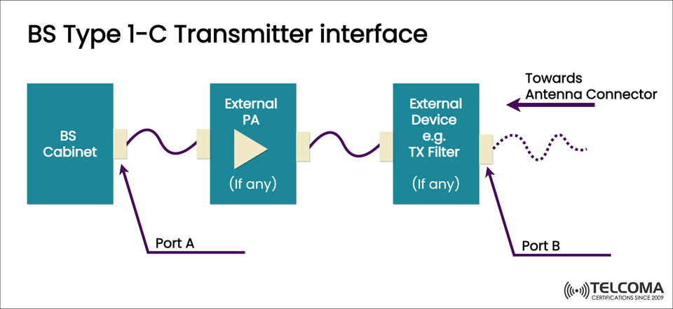
The Base Station (BS) Cabinet is the core of the radio system, housing various critical subsystems:
Baseband Unit (BBU): Manages signal processing, modulation, and digital encoding.
Radio Unit (RU) or Transceiver Module: Converts digital baseband signals into analog RF signals.
Local Control and Power Systems: Regulate performance and power distribution.
At Port A, the signal exits the BS cabinet as a low-power RF signal ready for amplification. This interface point allows for testing the transmitter output before it reaches any external amplification or filtering devices.
Key functions at this stage include:
Signal generation and modulation
Frequency conversion (baseband to RF)
Initial gain and linearization
Ensuring compliance with spectral masks prior to amplification
- External Power Amplifier (PA): Boosting the Signal
After leaving Port A, the signal may go through an External Power Amplifier (PA) — if necessary. This step is optional and depends on the deployment architecture and the required transmit power.
Role of the External PA:
Amplification: Raises RF power to levels suitable for over-the-air broadcast.
Linearization: Preserves signal integrity and avoids distortion or intermodulation.
Efficiency Optimization: Modern PAs (like Doherty or GaN-based) are engineered for high efficiency and minimal heat output.
The external PA ensures that the BS meets regulatory power standards and coverage requirements without putting too much strain on internal transmitter components.
Typical configurations:
Parameter Description Input Power (from BS)A few dBm Output Power (to TX Filter)Tens of watts or moreGain40–60 dB typical Location Outdoor or near antenna for RRH setups
- External Device – TX Filter or Duplexer
Once amplified, the signal proceeds to another optional stage — the External Device, usually a Transmit (TX) Filter or Duplexer.
Purpose of TX Filtering:
Eliminate Out-of-Band Emissions: Helps avoid interference with nearby channels or bands.
Conform to Spectrum Regulations: Ensures that the transmitted signal is within emission limits.
Enhance Co-location Performance: Reduces interference with neighboring cells or operators sharing the same tower.
Combine Frequency Bands: Duplexers or combiners allow multiple frequency bands to utilize one antenna system.
By this point, the RF signal is fully conditioned and ready to be passed to the antenna connector for over-the-air transmission.
- Port B and the Path Toward the Antenna Connector
Port B identifies the measurement point after all external devices (PA, filter, etc.). This interface signifies the final transmit output prior to the antenna system.
Testing at Port B enables engineers to verify:
Output power compliance
Spectrum mask performance post-filtering
Proper functioning of external RF components
Once the signal leaves Port B, it travels via coaxial cables or waveguides toward the antenna connector, where it radiates into the air interface — completing the transmission path.
BS Type 1-C vs. Other Base Station Types
To appreciate the structure of Type 1-C, let’s briefly compare it with other transmitter types defined by 3GPP and industry standards:
Type Description External Devices Measurement Port Type 1-AEntire transmitter inside BS cabinet None Antenna connector Type 1-BExternal PA only PA Port A before PA Type 1-CExternal PA and external filter PA + TX Filter Port A (pre-PA) and Port B (post-filter)Type 1-DDistributed system (Remote Radio Head)Integrated remote PA Typically at RRH output
The Type 1-C interface allows for flexibility in network design, enabling operators to tailor external RF stages according to specific performance or compliance aims.
- Applications and Benefits
Key Applications:
Macro Base Stations: Where high output power is necessary to cover larger areas.
Shared Infrastructure: When multiple operators share antenna systems.
Flexible Deployments: Enables modular design — allowing for straightforward upgrades or replacements of amplifiers and filters.
Benefits:
Enhanced Maintainability: Convenient testing at Port A and Port B.
Optimized Power Handling: External PAs can be adjusted for specific coverage requirements.
Regulatory Compliance: TX filters ensure emissions remain within licensed spectrum limits.
Scalability: Perfect for expanding network capacity without replacing entire cabinets.
- Testing and Compliance Considerations
Telecom professionals frequently conduct tests at Port A and Port B to ensure transmitter performance.
Typical Measurements:
Test Parameter Measured At Purpose Output Power Port B Verify transmit power level Spectrum Emission Mask Port B Check compliance with standards PA Gain and Linearity Port A and Port B Evaluate amplifier performance Insertion Loss Port B Assess filter losses VSWR / Return Loss Port B Ensure good impedance matching
Testing at both ports helps in identifying whether issues arise from the cabinet, amplifier, or external filter.
- Integration with Modern 5G and Open RAN Systems
As networks transition toward 5G NR and Open RAN frameworks, the Type 1-C transmitter interface continues to play a significant role. It provides a clear separation between digital and analog RF domains, facilitating:
Vendor Interoperability: Different vendors can supply PAs or filters compatible with standardized ports.
Ease of Upgrades: Operators can replace external amplifiers or filters without needing to modify the core BS cabinet.
Energy Efficiency: Intelligent external PAs can adjust output dynamically based on traffic load.
In Open RAN setups, these external elements may even be managed remotely through software interfaces for adaptive beamforming and energy management.
Conclusion
The BS Type 1-C Transmitter Interface is a key element of modular and high-performance base station design. By defining clear transmitter ports (A and B) and permitting external power amplifiers and filters, it ensures flexibility, maintainability, and compliance with regulations.
For telecom engineers, grasping this interface is vital for network optimization, troubleshooting, and system integration — particularly as the industry progresses toward open, software-defined radio access networks.
In summary, the BS Type 1-C configuration connects internal baseband processing with the real-world RF environment — ensuring that each signal transmitted from the antenna is strong, accurate, and regulatory compliant.