
Understanding the Functional Architecture of the EPS Network in LTE
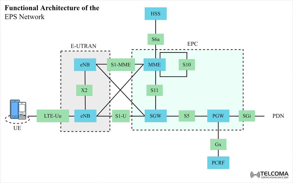

Functional Architecture of the Evolved Packet System (EPS) in LTE
The Evolved Packet System (EPS) outlines the LTE equipment that underlies the ultra-fast mobile data connectivity. EPS is comprised of two domains:
Evolved Universal Terrestrial Radio Access Network (E-UTRAN)
Evolved Packet Core (EPC)
To make sense of this functional architecture diagram, it is beneficial to explain each of the components and joining interfaces for the benefit of telecom people and tech-savvy people.
User Equipment (UE)
The User Equipment (UE) is a general term used for end devices (smartphones, tablets, connected devices, etc.) and connects to LTE via the LTE-Uu interface, which is defined in 3GPP TS 36.401 and provides the logical link to the eNodeB on the radio interface.
E-UTRAN (Radio Access Network)
E-UTRAN handles all radio access and any radio aspects of the connection between the UE and the EPC.
Main Component:
eNodeB (eNB)
eNodeB's responsibilities include:
Access and bandwidth control of radio resources.
Management of scheduling.
Management of mobility (ie; Handover processes).
The eNodeB interfaces directly with the EPC in 2 ways using the S1 connections, and can connect to other eNB's via the X2 connection, also referred to as the handover connection, and for "Load Balancing."
The key interfaces are:
LTE-Uu - UE ↔ eNB (Radio Link)
S1-MME interface - eNB ↔ MME (control signaling interface)
S1-U interface - eNB ↔ SGW (user data interface)
X2 interface - eNB ↔ eNB (handover support, and Load Balancing)
- EPC (Core Network)
Evolved Packet Core, is all about handling mobility management, session management, standalone authentication, and routing the information in the form of IP packets.
Main Components:
MME (Mobility Management Entity): Manages signaling, mobility management, and authentication. Connects to HSS via S6a and to SGW via S11.
HSS (Home Subscriber Server): Home subscrition information is stored in centralized database.
SGW (Serving Gateway): Routes user data between eNB and PGW. Provides data transfer functionality between the eNB and the PGW within the packet core.
PGW (Packet Data Network Gateway): Connects EPC to external Packet Data Networks (PDN). This includes provides the connection to standard internet through SGi interface to external PDNs.
PCRF (Policy and Charging Rules Function): Sets and manages QoS and charging policies between the PGW and the PCRF via Gx interface.
4. Interfaces in EPC Interface Connects Function
S6a MME ↔ HSS Authentication and subscriber info
S10 MME ↔ MME Inter-MME mobility
S11 MME ↔ SGW Bearer management
S5 SGW ↔ PGW User data, transfer
SGi PGW ↔ PDN Access to external networks
Gx PGW ↔ PCRF Policy and charging control 5.
How It All Works Together The UE connects to the eNodeB over LTE-Uu. The eNodeB can establish radio access and will relay MME with control signals via S1-MME interface. User data is forwarded from the eNodeB to the SGW via S1-U interface.
The SGW interacts with the PGW via S5 to route packets. The PGW allows access to the internet over the SGi interface, while the PCRF sets the appropriate QoS and charging policies.
Conclusion
The EPS Network architecture achieves seamless, high-speed LTE connectivity through an effectively split functional model between the E-UTRAN and EPC. Having an understanding of the components and the interfaces between them will help telecom professionals effectively manage performance and resolve connectivity issues.
6. Function of Components in EPS
E-UTRAN – eNodeB Functions
Radio Resource Management (RRM): The eNodeB allocates the spectrum efficiently with respect to the users.
Packet Scheduling: The eNodeB prioritizes packets via QoS Class Identifier (QCI)
Mobility Control: The eNodeB executes handovers with X2 or S1 signal.
Encryption & Integrity Protection: The eNodeB follows the security algorithm as defined by the MME.
EPC – Core Component Functions
MME:
Manages the attach/detach procedures
Manages bearer activation state.
Manages idle-to-Connected state transitions.
SGW:
Provides local mobility anchoring in the case of inter-eNodeB handovers.
Buffers data from downlink paths in idle states.
PGW:
Assigns IP-addresses to UEs.
Manages deep packet inspection (DPI) policies.
PCRF:
Manages policies in real time, on a dynamic basis, and based on the type of service; e.g., Voice over LTE vs. Video streaming.
HSS:
Stores profiles of subscribers, including IMSI, subscribed services, and roaming restrictions.
7. EPS Interfaces in Real-Life Scenarios
VoLTE call setup:
MME authenticates the user via the HSS
PCRF implements VoLTE QoS settings using the PGW
Data and signaling flows on the same path with S1-U and S1-MME.
eNodeB Handover:
The X2 interface allows a fast handover between neighboring cells without going through the MME.
If X2 is not available, an S1-based handover will occur.
Roaming:
The MME interacts with a visited HSS or home HSS over an IP-based Diameter protocol over S6a.
- Performance Optimization in EPS Networks
As operators define low latency and high throughput with mobility, they optimize:
X2 handover efficiency to minimize MME signaling traffic.
QoS-aware scheduling at the eNodeB, to prioritize premium services.
SGW and PGW and monitor for load on MME to avoid bottleneck.
Smart PCRF policies for allocating bandwidth allocations.
- The Future: EPS to 5G Core (5GC)
EPS provides the base structure for LTE/LTE Advanced; EPS also serves as a transition to 5G. Many EPC components (e.g. PGW, PCRF), have equivalent logical structures in the 5G Core Network (5GC) with a component-based focus on Service Based Architecture (SBA).
MME → AMF (Access and Mobility Management Function)
SGW/PGW → UPF (User Plane Function)
PCRF → PCF (Policy Control Function)
Take Aways
EPS = E-UTRAN + EPC. Designed for all IP LTE Networks.
The separation between control plane (MME, S6a, S11, S10) and user plane (SGW, PGW, S1-U, S5) provides operational efficiencies.
Interfaces are standardized to promote inter-operability across vendors.
Closing Thoughts
Familiarity with the functional architecture of EPS is key to the construction, maintenance, and future evolution of LTE networks. From the UE-to-EPC journey to the enforcement of policy control and QoS, every functional area plays an important role in providing a quality mobile experience. Even as networks evolve to 5G, the principles of EPS will continue to impact future architectures.