
Understanding the GSM Mobile Phone Block Diagram: Key Components and Their Functions

Understanding the GSM Mobile Phone Block Diagram
The GSM (Global System for Mobile Communication) is a groundbreaking technology in the world of telecommunications. It really set the stage for modern cellular networks by establishing a standard for how mobile devices connect, send, and receive information over radio channels.
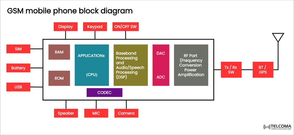
A GSM mobile phone isn’t just about sending and receiving signals; it’s actually a complex electronic system made up of several interconnected components. The diagram provided offers a straightforward view of this setup, illustrating how digital processing, RF conversion, and various interfaces come together to form a functional GSM handset.
Overview of the GSM Mobile Phone Architecture
A GSM mobile phone can be generally categorized into three main sections:
Digital Section – This includes the CPU, memory, DSP, and CODEC.
Analog/RF Section – This part deals with frequency conversion, amplification, and transmitting through the antenna.
Peripheral and Power Section – Houses the display, keypad, microphone, speaker, camera, SIM card, and battery.
- Central Components: CPU and Memory (Applications Section)
At the heart of every GSM phone is the Applications Processor, or CPU, which oversees the main control functions of the device.
CPU (Central Processing Unit):
Runs the operating system and software applications.
Manages input/output devices (like the keypad, display, camera).
Works alongside the Baseband Processor for tasks related to communication.
Memory Units:
RAM (Random Access Memory):
Temporarily holds the programs and data currently in use.
Offers workspace for the CPU while it’s executing tasks.
ROM (Read-Only Memory):
Stores firmware, the operating system, and essential boot code.
Contains predefined configurations and default network settings.
Together, the CPU, RAM, and ROM create the control and application subsystem, managing the smartphone’s user interface and logic.
- Baseband and Audio Processing (DSP Section)
The Baseband Processing and Audio/Speech Processing (DSP) block is where the signal-level operations take place, enabling communication between the user and the network.
Baseband Processor (BBP):
Converts high-level digital data into low-level signals suitable for radio transmission.
Handles modulation, demodulation, channel coding, and decoding.
DSP (Digital Signal Processor):
Works with voice signals: including compression, echo cancellation, and filtering.
Manages speech encoding (vocoding) for efficient transmission.
Synchronizes timing and equalizes signals to maintain quality.
In simple terms, while the CPU runs the apps, the DSP makes sure communication over the GSM network is clear and in sync.
- CODEC: Bridging Analog and Digital Domains
The CODEC (Coder-Decoder) functions as a bridge between the analog world (like the microphone and speaker) and the digital processing world (DSP and CPU).
Functions of the CODEC:
Turns analog speech from the microphone into digital signals (encoding).
Converts received digital signals back into analog for the speaker (decoding).
Maintains sound quality and reduces noise during these conversions.
This step is crucial for accurately representing human voice signals in digital form without too much distortion or delay.
- ADC and DAC: Signal Conversion Units
The ADC (Analog-to-Digital Converter) and DAC (Digital-to-Analog Converter) are key for connecting the digital and analog pathways.
ADC (Analog-to-Digital Converter):
Translates analog baseband signals into digital data for processing by the DSP.
Used for voice input and incoming signal paths.
DAC (Digital-to-Analog Converter):
Converts processed digital baseband data back into analog signals before transmitting.
Together, the ADC and DAC ensure smooth transitions between digital signal processing and radio transmission.
- RF Section: Frequency Conversion and Power Amplification
The RF Part is tasked with changing processed baseband signals into high-frequency radio signals suitable for the GSM network.
Key Functions of the RF Section:
Up conversion: Shifts the baseband (low-frequency) signal to a carrier frequency (like 900 MHz or 1800 MHz).
Down conversion: Converts high-frequency received signals back to baseband.
Power Amplification: Boosts signal strength before transmission.
Filtering: Eliminates unwanted harmonics and noise for clearer signals.
This part ensures the signals sent through the antenna meet GSM frequency and power regulations.
- Tx/Rx Switch and Antenna Interface
The Tx/Rx Switch (Transmit/Receive Switch) manages how signals flow between the transceiver circuitry and the antenna.
Functionality:
In transmission mode, it connects the power amplifier output to the antenna.
In reception mode, it directs incoming signals from the antenna to the receiver.
Prevents any interference between sending and receiving signals.
Antenna:
Emits RF energy into space during transmission.
Receives electromagnetic waves when in reception mode.
This switch allows for full-duplex communication, which is a key feature of GSM networks.
Peripheral Interfaces and External Connections
GSM phones interact with users and external devices through various peripheral components:
Component Function Display Shows the user interface, messages, and call info. Keypad User input for dialing and navigating menus. Camera Captures images and video. Speaker & Mic Audio output and input. SIM Card Stores subscriber identity, IMSI, and authentication keys. Battery Provides power to all circuits. USB Port Used for charging and data exchange.BT/GPS Module Gives Bluetooth connectivity and GPS positioning. ON/OFF Switch Turns the device on or off.
Each of these components works together through control signals and data buses managed by the CPU and DSP.
- Power Management and Battery Interface
The Battery delivers the necessary DC voltage to the phone’s subsystems.
Modern GSM phones come with:
Voltage regulators that ensure consistent power supply.
Charging circuits accessed via the USB port.
Power control ICs that manage sleep modes and battery health.
Good power management helps extend battery life while ensuring strong signal transmission.
- Bluetooth (BT) and GPS Integration
While GSM is primarily designed for voice calls, modern devices also feature Bluetooth (BT) and GPS modules.
Bluetooth (BT): Facilitates wireless data transfer and hands-free audio.
GPS (Global Positioning System): Offers location tracking and navigation.
These modules connect with the RF front-end and utilize the same antenna system, coordinated by the CPU.
Signal Flow Summary
To wrap it up, here's how the operation flows:
Voice Input: Microphone → CODEC → DSP → RF Section → Antenna (for sending).
Voice Output: Antenna → RF Section → DSP → CODEC → Speaker (for receiving).
Control: CPU oversees DSP, user interfaces, and RF management.
Power & Connectivity: Battery, SIM, and USB facilitate system operation and communication.
Conclusion
The GSM mobile phone block diagram is a valuable tool for grasping how mobile communication systems fundamentally operate.
From digital baseband processing through RF amplification to signal conversion and managing peripherals, each component plays an important role in enabling smooth communication between users and the network.