
Understanding the Multiple Layers of the OTN Network: ODU, OCh, and WDM Explained

The Different Layers of the OTN Network
In today’s world, modern communication networks rely heavily on optical fiber systems to handle the increasing demand for data. Whether it’s high-speed internet, cloud connections for businesses, or 5G transport, data has to travel long distances quickly and reliably. This is where Optical Transport Network (OTN) technology, as defined by ITU-T G.709, becomes crucial.
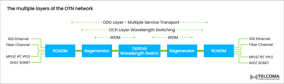
The diagram titled “The multiple layers of the OTN network” clearly illustrates how the various layers within the OTN framework work together to ensure smooth transport of different client signals, including Ethernet, Fiber Channel, MPLS/IP, and SDH/SONET.
Introduction to Optical Transport Network (OTN)
The Optical Transport Network (OTN) is designed as a digital wrapper that standardizes how multiple client signals travel over optical fiber. Essentially, it provides a transparent way to transport various protocols, facilitating high-capacity, low-latency, and error-protected data transfer.
OTN has three main functions:
Encapsulation: It wraps client signals (such as Ethernet or SONET) into OTN frames.
Multiplexing: It combines several lower-rate signals into one higher-rate channel.
Transport & Switching: It manages optical paths throughout the network using tools like ROADMs and Optical Wavelength Switches.
The diagram shows how OTN brings together different services into a robust optical backbone while preserving signal integrity and scalability.
Client Signals in OTN Networks
On both sides of the diagram, you can see client signals entering and leaving the network. They include:
10G Ethernet for business and data center connectivity.
Fiber Channel for Storage Area Network (SAN) links.
MPLS/IP/VPLS for carrier-grade packet transport.
SDH/SONET for older synchronous transport systems.
These signals are mapped into OTN containers (ODUk) when they first enter the network, often through a Reconfigurable Optical Add-Drop Multiplexer (ROADM) or an OTN gateway.
Once encapsulated, the data travels through the network layers as OTN signals, ensuring error detection, path monitoring, and overall management from start to finish.
Understanding the Three Layers of OTN
The image highlights three fundamental layers of OTN that work together to transport data:
ODU Layer – Multiple Service Transport
OCh Layer – Wavelength Switching
WDM Layer – Physical Optical Multiplexing
Let’s discuss each layer in detail.
3.1. ODU Layer – Multiple Service Transport
At the top of our diagram, the ODU (Optical Data Unit) layer serves as the digital transport layer of OTN.
In this layer, client signals are mapped, multiplexed, and transported across the optical network. The ODU layer is responsible for delivering services from end to end while keeping track of performance.
Roles of the ODU Layer:
Encapsulating client signals (such as Ethernet, SDH, IP, etc.) into ODUk frames.
Multiplexing: Combining multiple lower-order ODUs (like ODU0, ODU1) into higher-order containers (like ODU2, ODU4).
Error management: Using Forward Error Correction (FEC) and BIP-8 checks to ensure data accuracy.
OAM functions: Operations, Administration, and Maintenance features for quality control.
Example:
A 10G Ethernet signal gets mapped into an ODU2 frame, which can then be transmitted over an OTN link running at 10 Gbps or more.
This layer focuses solely on digital data transport and multiplexing, independent of the physical wavelength used.
3.2. OCh Layer – Optical Channel Wavelength Switching
The OCh (Optical Channel) layer is just below the ODU layer, concentrating on the optical signal itself, specifically the individual wavelengths (λ) that carry ODU data along the fiber.
Each OCh corresponds to a specific wavelength in the Dense Wavelength Division Multiplexing (DWDM) setup.
Roles of the OCh Layer:
Assigning wavelengths: Each optical signal (ODUk payload) is modulated onto a specific wavelength.
Switching: Tools like ROADMs and Optical Wavelength Switches manage how optical channels are routed within the network.
Monitoring signal quality: Keeping an eye on optical power levels, OSNR (Optical Signal-to-Noise Ratio), and polarization effects.
Key Devices at This Layer:
ROADM (Reconfigurable Optical Add-Drop Multiplexer): It dynamically adds, drops, or reroutes optical channels without converting to electrical signals.
Optical Wavelength Switches: These allow for flexible wavelength-level connections and optimize traffic.
Example:
If a network carries several 100G channels, each channel may use a different wavelength (like λ1, λ2, λ3), and the OCh layer ensures they are switched correctly to their destinations.
3.3. WDM Layer – Physical Optical Multiplexing
At the foundation of the optical hierarchy is the WDM (Wavelength Division Multiplexing) layer, which provides the physical optical transport medium.
This layer is all about combining and transmitting different wavelengths over a single fiber, significantly boosting overall capacity.
Roles of the WDM Layer:
Combining multiple wavelengths (each carrying an OCh signal) into a single optical fiber.
Amplifying and managing dispersion via devices like EDFAs (Erbium-Doped Fiber Amplifiers).
Signal regeneration through strategically placed regenerators over long distances.
Key Equipment:
Regenerators: They amplify and reshape signals to counteract attenuation and dispersion.
WDM Multiplexers/Demultiplexers: These devices combine and separate wavelengths at network nodes.
Example:
A WDM system could send 80 wavelengths, each with a capacity of 100 Gbps, totaling around 8 Tbps per fiber pair.
The Role of Key Network Elements (ROADM, Regenerator, Optical Switch)
ROADM (Reconfigurable Optical Add-Drop Multiplexer)
Allows for dynamic management of wavelengths.
Facilitates non-disruptive network adjustments.
Crucial for mesh and flexible-grid networks.
Regenerator
Restores optical signals after long-distance journey.
Conducts 3R functions: Reamplify, Reshape, and Retime.
Maintains signal quality over hundreds of kilometers.
Optical Wavelength Switch
Delivers high-capacity routing for wavelengths.
Supports optical cross-connect (OXC) tasks.
Essential for creating transparent optical networks.
These components ensure that the digital data flow (ODU) and the optical wavelength flow (OCh/WDM) stay in sync and efficient.
Why Layered Architecture Matters in OTN
A layered OTN design brings several key benefits:
Scalability: It readily accommodates higher bit rates (100G, 400G, 800G, and beyond).
Interoperability: Standardized interfaces help create multi-vendor environments.
Resilience: Layered fault management ensures continuous service.
Efficiency: Optimizes fiber capacity through advanced multiplexing and switching.
Transparency: Client signals remain unchanged, no matter the protocol.
This structure allows providers to offer multiple services on a single optical framework, cutting costs and enhancing flexibility.
Conclusion
The Optical Transport Network (OTN) is truly a remarkable aspect of modern telecommunications — a multi-layered system that guarantees high-speed, reliable, and scalable data transport.
The diagram of “The multiple layers of the OTN network” beautifully demonstrates how the ODU, OCh, and WDM layers work together to manage a variety of client services on a single optical platform.
By separating digital, optical, and physical functions, OTN provides efficiency, transparency, and flexibility — all vital components for the next-generation transport networks powering 5G, cloud services, and data center ecosystems.