
Understanding UPF Interactions in 5G: Downlink and Uplink Data Transfer Explained

UPF Interactions in 5G: How Downlink and Uplink Data Transfer Works
The User Plane Function (UPF) plays a central role in the 5G Core (5GC), managing the flow of data packets between the 5G NodeB (gNB) and external networks. This blog will break down how UPF handles the initiation of both downlink and uplink data transfer, using the diagram provided as a guide.
We'll look closely at the Packet Forwarding Control Protocol (PFCP) signaling that takes place between the Session Management Function (SMF) and UPF—this interaction is crucial for maintaining smooth data sessions in standalone 5G networks.
Background: Understanding the Role of UPF in 5G
The UPF is a vital element of the Service-Based Architecture (SBA) in the 5G Core. It serves as the anchor point for the data plane, overseeing packet routing, forwarding, buffering, and quality of service (QoS) enforcement for user data sessions.
Some key responsibilities of the UPF include:
Routing and forwarding packets between the gNB and the data network
Enforcing policies and shaping traffic
Temporarily holding downlink packets during idle or transitional states
Reporting usage data for billing and analytics
Managing sessions in partnership with the SMF via the N4 interface
By coordinating this way, user traffic flows smoothly as soon as a Protocol Data Unit (PDU) session is established.
Overview of the Downlink and Uplink Transfer Procedure
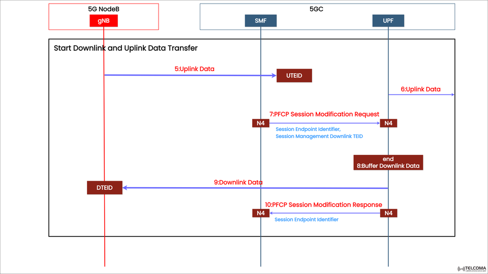
Once the user registers and sets up the PDU session, the network moves on to active data transfer. The diagram shows how data starts flowing between three main entities:
5G NodeB (gNB) – the access point connecting to user equipment (UE)
SMF (Session Management Function) – the control-plane entity that manages UPF actions
UPF (User Plane Function) – the user-plane entity that forwards the actual user data
The process focuses on kicking off uplink and downlink data transfers and the PFCP exchanges that handle buffering and session adjustments.
Step-by-Step Breakdown of the Procedure
Step 5: Uplink Data from gNB to SMF
When the UE has data to send upstream, it sends it to the gNB, which packages it up and passes it along the N3 interface to the UPF. This data packet includes a Uplink TEID (U-TEID)—a Tunnel Endpoint Identifier assigned when the session was set up.
Purpose: This packet notifies that the UE is active and ready for data flow.
Entities involved: gNB → SMF (via UPF)
Key identifier: UTEID (Uplink TEID)
The SMF notes the arrival of uplink data and might need to tweak PFCP rules for managing downlink delivery.
Step 6: Uplink Data Forwarded to UPF
The uplink packet continues from the SMF to the UPF based on the current PFCP session rules. The UPF processes the data and can also use it as a trigger to start sending any previously buffered downlink traffic.
Purpose: It signals to the UPF that the UE is reachable and ready for any buffered data.
Interface used: N4 between SMF and UPF
At this point, the N4 interface allows control signaling, enabling the SMF to instruct the UPF to adjust forwarding rules or release buffered data.
Step 7: PFCP Session Modification Request (SMF → UPF)
Next, the SMF sends a PFCP Session Modification Request to the UPF, including parameters that change or update the existing PFCP session context.
Key Information Elements (IEs) include:
Session Endpoint Identifier
Session Management Downlink TEID
Updates to forwarding rules or buffer status
This modification enables the UPF to shift from buffering mode to active data forwarding, leading to a resumption of downlink data transfer.
Step 8: End of Buffering Downlink Data
Once the PFCP session modification is completed, the UPF stops buffering and begins releasing the stored downlink packets to the UE via the gNB.
Buffer Downlink Data (end): This indicates that the buffered traffic is now on its way to the user.
Importance: This step is crucial for ensuring that no data is lost during transitions from idle to active states, leading to a better user experience with uninterrupted connectivity.
Step 9: Downlink Data to gNB
With the buffering finished, the UPF sends downlink data packets to the gNB using the Downlink TEID (D-TEID) established during the PDU session setup.
Entities involved: UPF → gNB
Interface: N3
Key function: Moving data from the core network to the user device
At this stage, user traffic starts flowing in both directions, marking the switch to the active data phase.
Step 10: PFCP Session Modification Response (UPF → SMF)
Finally, the UPF sends a PFCP Session Modification Response back to the SMF over the N4 interface.
Purpose:
Confirms that the requested session changes have been successfully applied
Provides the final Session Endpoint Identifier to verify the modification
With this, the coordination between control-plane and user-plane is all set, and the session is fully operational for ongoing user data transfer.
Key Concepts and Interfaces
PFCP (Packet Forwarding Control Protocol): Used between SMF and UPF to manage sessions, create rules, and adapt user-plane behavior on the fly.
N4 Interface: This logical interface connects the SMF and UPF for PFCP signaling.
TEID (Tunnel Endpoint Identifier): A unique identifier for GTP-U tunnels in the user plane, helping to separate different data streams.
Buffering Mechanism: Helps prevent packet loss when the UE moves between different states like idle, inactive, or active.
Importance in 5G Network Performance
Managing uplink and downlink data transfer efficiently leads to:
Low latency: Quick shift from idle to active data transfer
Seamless user experience: No data loss or interruptions
Optimized network resources: Dynamic session management avoids unnecessary signaling
Enhanced reliability: Buffering ensures consistent delivery, even amid mobility events
These processes are crucial in supporting 5G’s varied service offerings, including enhanced Mobile Broadband (eMBB), Ultra-Reliable Low Latency Communication (URLLC), and Massive IoT.
Conclusion
The mechanics of starting downlink and uplink data transfer in 5G—driven by UPF and SMF interactions through PFCP signaling—form the backbone of effective 5G data management.
By managing session changes, buffering, and tunnel functions, the network maintains data continuity and high throughput, even in changing conditions.
For telecom engineers and professionals in 5G, understanding these UPF interactions offers valuable insight into how modern mobile networks achieve exceptional reliability, speed, and scalability.