
Understanding UPF — User Plane Function Interactions in the 5G Core Network

Understanding UPF — User Plane Function Interactions
The User Plane Function (UPF) acts as the data-forwarding engine of the 5G Core (5GC). Essentially, it connects the 5G radio network (gNB) with the data network (DN), overseeing how user traffic flows, ensuring Quality of Service (QoS), and managing packet routing.
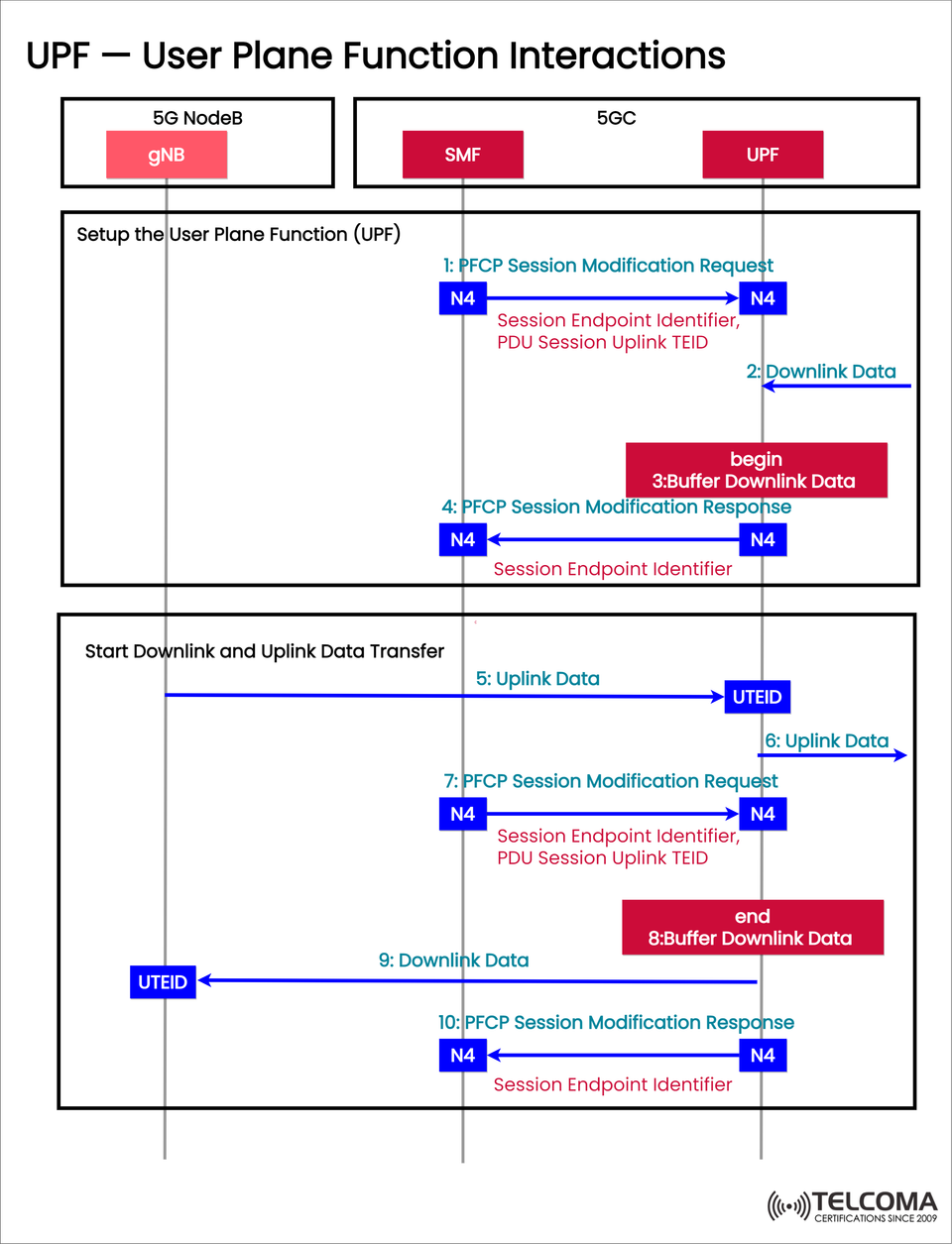
In the diagram above, you can see how the UPF collaborates with the SMF (Session Management Function) and gNB (5G NodeB) during the setup, buffering, and activation of user plane sessions. Grasping this interaction is vital for smooth data transfer in 5G systems — right from session initiation to the activation of user traffic.
In this article, we're diving deep into UPF interactions, PFCP message flows, and the overall data transfer process within a 5G context.
Phase 1: Configuring the User Plane Function
When a new PDU (Protocol Data Unit) session kicks off, the SMF needs to set up the UPF so it can properly forward user packets. This setup is done using PFCP messages across the N4 interface.
Step 1: PFCP Session Modification Request
Sender: SMF
Receiver: UPF
Interface: N4
Purpose: Set or modify the UPF session for a PDU context.
The PFCP Session Modification Request includes:
Session Endpoint Identifier – Uniquely identifies the PFCP session.
PDU Session Uplink TEID – Points out the tunnel endpoint for uplink data.
This message prepares the UPF for user data forwarding by establishing the necessary GTP-U tunnels and QoS parameters.
Step 2: Incoming Downlink Data
While the UPF sets up, downlink data (from the Data Network to the UE) might start arriving. Since the user plane isn’t fully active yet, the UPF can’t forward this data just yet.
Step 3: Start of Downlink Data Buffering
The UPF buffers the incoming downlink packets temporarily.
This avoids packet loss before the session is fully active.
Buffering helps ensure a smooth start to the data session once the uplink paths are ready.
Here, you can see the UPF’s smart handling of temporary states — a significant upgrade from old EPC (Evolved Packet Core) systems.
Step 4: PFCP Session Modification Response
Sender: UPF
Receiver: SMF
Interface: N4
Purpose: Confirm that configuration was successful.
The UPF sends a PFCP Session Modification Response, confirming:
Session has been successfully configured.
Session Endpoint Identifier has been validated.
UPF is ready to manage user data traffic.
At this moment, the user plane setup phase is complete.
Phase 2: Commencing Downlink and Uplink Data Transfer
Once the UPF is set up, it can begin to relay data between the UE and the Data Network.
Step 5: Starting Uplink Data
Sender: gNB (UE → Network)
Receiver: UPF
Purpose: Initiate uplink transmission.
Uplink packets from the UE are transmitted to the UPF via GTP-U tunnels, identified by Uplink TEID (UTEID).
Step 6: Uplink Data Forwarding
The UPF forwards the uplink data to the Data Network (DN).
It uses routing rules and QoS parameters that the SMF defined during setup.
This officially starts the bi-directional data flow.
Step 7: Second PFCP Session Modification Request
Sender: SMF
Receiver: UPF
Purpose: Update UPF configuration post-uplink data commencement.
The SMF sends another PFCP Session Modification Request to notify the UPF that the UE is active and it can now continue with the buffered downlink traffic. This ensures the uplink and downlink paths are synchronized.
Step 8: Concluding Downlink Data Buffering
Once the uplink is active, the UPF can release the previously buffered downlink data, sending it to the UE through the gNB.
This signifies the shift from buffering to full data transfer mode, ensuring everything flows smoothly with no packet loss or delays as the UE gets ready to receive.
Step 9: Downlink Data Transfer
Sender: UPF
Receiver: gNB
Purpose: Forward downlink packets to UE.
Using the Uplink TEID (UTEID) assigned earlier, the UPF sends data to the gNB, which then delivers it over the radio connection to the UE.
This confirms that both uplink and downlink data flows are fully functional now.
Step 10: Final PFCP Session Modification Response
Sender: UPF
Receiver: SMF
Purpose: Confirm successful modification.
The UPF sends a final PFCP Session Modification Response to confirm that the session state has been updated.
This way, it guarantees that all session endpoints and TEIDs are properly synced between the SMF and UPF.
Recap of UPF Interaction Steps
StepInterfaceMessageDescription1N4PFCP Session Modification Request Set up UPF session2—Downlink Data Data received pre-activation3—Buffer Downlink Data (Begin)Temporarily store downlink data4N4PFCP Session Modification Response Confirm UPF setup5—Uplink Data Send UE data to UPF6—Uplink Data Forwarding UPF forwards data to network7N4PFCP Session Modification Request Update session for active state8—Buffer Downlink Data (End)Release stored downlink data9—Downlink Data Deliver packets to UE10N4PFCP Session Modification Response Confirm session update
Key Takeaways from UPF Interactions
PFCP is Key for Control: The N4 interface with PFCP messages enables flexible, real-time control of UPF operations by the SMF.
Buffering Avoids Packet Loss: The UPF smartly buffers downlink data until the uplink path for the UE is ready.
Dynamic Session Updates: Multiple PFCP modification requests help keep control and user planes in sync.
Smooth Data Flow: As soon as both paths are operational, data moves seamlessly between the UE and the network.
UPF's Real-World Importance
The UPF is fundamental to many of the standout features of 5G:
Network Slicing: Separates user data depending on service type (eMBB, URLLC, IoT).
Edge Computing: Positions UPFs closer to users for ultra-low latency.
Policy Enforcement: Collaborates with PCF and SMF to enforce QoS and charging regulations.
Scalable Architecture: Allows for distributed deployment to optimize regionally.
Final Thoughts
The User Plane Function (UPF) is vital to the data delivery architecture of 5G. Through a series of PFCP-driven interactions with the SMF and coordination of data flow with the gNB, it ensures reliable, efficient, and policy-guided user traffic transmission.
From buffering downlink packets to ensuring uplink sessions are in sync, the UPF guarantees precise delivery of each piece of data. As 5G networks continue to evolve towards edge computing and network slicing, the UPF will be crucial for achieving ultra-reliable and low-latency communication (URLLC).