
5G NR FR1 Maximum Transmission Bandwidth Configuration Explained

Complete Guide to 5G NR FR1 Maximum Transmission Bandwidth Configuration
As 5G networks develop around the world, it’s becoming crucial for network planners, engineers, and telecom fans to understand how transmission bandwidth is set up. The maximum transmission bandwidth configuration dictates how many resource blocks (RBs) a 5G carrier can utilize, which directly impacts data speeds and how efficiently the spectrum is used.
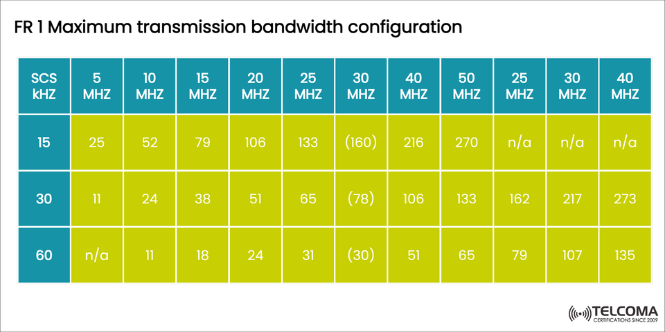
The image above illustrates the FR1 (Frequency Range 1) bandwidth setups, highlighting the relationship between subcarrier spacing (SCS) and channel bandwidth, and how they determine the number of resource blocks (NRBs).
In this article, we’ll dive into what the table means, the significance of SCS, how FR1 compares to FR2, and offer practical insights on deploying 5G.
Understanding 5G NR Frequency Ranges
5G NR works in two main frequency ranges:
Frequency Range Description Typical UseFR1Sub-6 GHz (410 MHz – 7125 MHz)Macro and mid-band coverageFR2mmWave (24.25 GHz – 71 GHz)High-capacity small cells
The image refers to FR1, which is currently the most widely used frequency range. It strikes a balance between coverage and capacity, making it a great option for extensive 5G rollout in both urban and suburban areas.
What Is the Transmission Bandwidth Configuration?
In 5G NR, the transmission bandwidth configuration specifies the maximum number of resource blocks (NRBs) available for a specific subcarrier spacing (SCS) and channel bandwidth.
Each resource block represents a set time-frequency grid that carries data, so the total number of resource blocks dictates how much information can be sent at once.
Key Components:
SCS (Subcarrier Spacing): The spacing between neighboring subcarriers in kHz.
Channel Bandwidth: The total spectrum allocated for the carrier.
NRB (Number of Resource Blocks): How many resource blocks can be transmitted.
Subcarrier Spacing (SCS) in 5G FR1
5G offers flexible subcarrier spacing, which means the system can adapt across various frequencies and deployment setups. The subcarrier spacing (SCS) is expressed as:
SCS = 15 kHz × 2μ
where μ is the numerology index (0, 1, 2, …).
SCS Options in FR1:
15 kHz (μ = 0): Best for lower frequency bands (<3 GHz), offering longer symbol durations and better coverage.
30 kHz (μ = 1): Strikes a good balance between capacity and coverage, common in mid-band 5G (3.5 GHz).
60 kHz (μ = 2): Used in higher FR1 frequencies (like around 6 GHz) for improved throughput and lower latency.
Analyzing the FR1 Maximum Transmission Bandwidth Table
The table showcases how many resource blocks (NRBs) can be configured for different SCS values (15, 30, and 60 kHz) across a range of channel bandwidths (from 5 MHz to 50 MHz and more).
SCS (kHz)5 MHz10 MHz15 MHz20 MHz25 MHz30 MHz40 MHz50 MHz15255779106133(160)2162703011243851(78)10613360N/A11182431(30)5165
Note: The values in parentheses may represent theoretical limits or special conditions that depend on specific implementations or spectrum availability.
Understanding the Table
A. For 15 kHz SCS
Perfect for low-frequency FR1 bands (like 600 MHz, 700 MHz).
Provides broad coverage and longer symbol durations, which is great for rural areas.
The number of NRBs increases with bandwidth — starting at 25 RBs at 5 MHz rising to 270 RBs at 50 MHz.
B. For 30 kHz SCS
Commonly found in mid-band 5G (e.g., n78 band around 3.5 GHz).
Balances capacity and latency well.
With a 20 MHz carrier, you get 51 NRBs, and 50 MHz can support 133 NRBs.
C. For 60 kHz SCS
Designed for higher-frequency FR1 deployments (like the 6 GHz range).
Offers lower latency and quicker symbol processing, but with less coverage per cell.
Fewer NRBs compared to 15 or 30 kHz because larger subcarrier spacing means fewer subcarriers fit in the same bandwidth.
Why These Values Matter
The number of resource blocks (NRBs) impacts:
Total available throughput
Modulation and coding scheme (MCS) efficiency
Scheduling granularity
User capacity
For example, doubling the bandwidth (from 20 MHz to 40 MHz) roughly doubles the available NRBs, which can boost data rates significantly — assuming the modulation and coding are sufficient.
Bandwidth Part (BWP) Considerations
In 5G NR, users don’t always use the entire bandwidth. Instead, they get a Bandwidth Part (BWP), which is a portion of the total NRBs.
This approach allows for:
Power efficiency for user equipment (UE).
Dynamic allocation for changing traffic needs.
Better performance in both wideband and narrowband setups.
Deployment Considerations
Low SCS (15 kHz):
Best for large cell coverage and deep indoor penetration.
Commonly used for anchor carriers in NSA (Non-Standalone) 5G.
Mid SCS (30 kHz):
Ideal for urban and suburban settings.
Frequently found in C-band (3.5 GHz) deployments — the global sweet spot for 5G.
High SCS (60 kHz):
Targeted for capacity-driven small cells.
Works well in high-frequency bands where coverage area is typically smaller.
Comparing FR1 and FR2 Bandwidth
ParameterFR1FR2Frequency Range410 MHz – 7.125 GHz24.25 GHz – 71 GHz Typical Bandwidth per Carrier Up to 100 MHz Up to 400 MHz Subcarrier Spacing15 / 30 / 60 kHz60 / 120 / 240 kHz Coverage Wide Limited Latency Moderate Low Use Case Coverage and mobility Capacity and ultra-high data rates
A Practical Example
Let’s look at a 5G NR carrier running at 3.5 GHz, with:
Channel Bandwidth: 100 MHz
SCS: 30 kHz
According to 3GPP specifications and following the table’s logic, the maximum NRBs would be 273 for a 100 MHz carrier. This setup is commonly seen in C-band 5G deployments, allowing for multi-gigabit speeds and efficient use of mid-band spectrum.
Key Takeaways
SCS and channel bandwidth together dictate how many resource blocks can be allocated in 5G NR.
15 kHz SCS provides wide coverage, while 30 kHz and 60 kHz enhance capacity and lower latency.
FR1 aims for a balance — broad coverage and reliable performance.
Effective bandwidth configuration ensures optimized spectrum use and maximum network efficiency.
Conclusion
The FR1 Maximum Transmission Bandwidth Configuration is a fundamental aspect of 5G NR radio design. It defines how spectrum resources are allocated, how much data can flow, and ultimately how users experience the network performance.
By grasping how subcarrier spacing (SCS) and channel bandwidth shape the number of resource blocks (NRBs), telecom experts can better design and optimize networks that achieve both solid coverage and high throughput — the core of what 5G promises.