
5G Standalone NAS and AS Security Procedures Explained: From RRC Setup Complete to SRB Ciphering

5G Standalone NAS and AS Security Setup: A Detailed Overview
In 5G Standalone (SA) networks, one of the most crucial steps during registration is ensuring a secure connection between the User Equipment (UE) and the 5G NodeB (gNB). After the RRC connection setup wraps up, the system shifts focus to NAS and AS-level security. This step is all about shielding signaling and user data from being intercepted or tampered with.
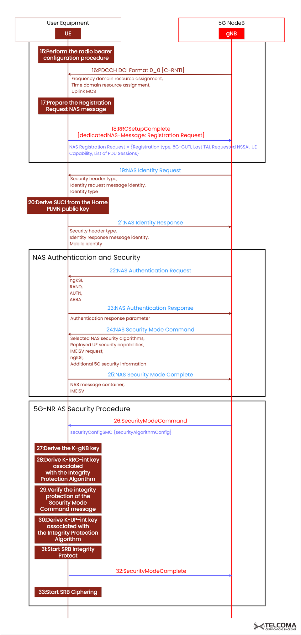
The diagram included here does a great job of showing this process, highlighting how the UE and gNB authenticate each other, derive encryption keys, and activate integrity protection and ciphering. In this article, we’ll break down each step featured in the image — from RRC Setup Complete to SRB Ciphering — explaining what each message and operation is for and how they flow together.
From RRC Setup to NAS Registration Request
Once the RRC connection is all set up, the UE moves on to the next steps for NAS registration and getting ready for authentication.
Step 15: Perform the Radio Bearer Configuration Procedure
After getting the RRCSetup message from the gNB, the UE kicks off the radio bearer configuration procedure. Here, the focus is on setting up Signaling Radio Bearer 1 (SRB1) for sending NAS messages back and forth between the UE and the gNB. At this stage, the RRC connection acts as a logical channel for the NAS signaling exchange ahead.
Step 16: PDCCH DCI Format 0_0 [C-RNTI]
The gNB sends out Downlink Control Information (DCI) Format 0_0 addressed to the UE’s C-RNTI, allocating resources for both uplink and downlink. This includes:
Frequency domain resource assignment
Time domain resource assignment
Uplink Modulation and Coding Scheme (MCS)
This scheduling allows the UE to efficiently transmit its RRCSetupComplete message.
Step 17: Prepare the NAS Registration Request
Before firing off the RRC Setup Complete, the UE puts together a NAS Registration Request message that covers:
Registration type (like initial registration, periodic update, etc.)
5G-GUTI (Globally Unique Temporary Identifier)
Last known Tracking Area Identity (TAI)
Requested NSSAI (Network Slice Selection Assistance Information)
UE capabilities
List of PDU sessions
This message kicks off the NAS-level registration process with the 5G Core (AMF).
Step 18: RRC Setup Complete with Dedicated NAS Message
The UE wraps the NAS Registration Request into an RRCSetupComplete message and sends it over to the gNB:
RRC Setup Complete [dedicated NAS-Message: Registration Request]
This message indicates that the RRC setup is complete, and the NAS-level registration can begin.
NAS Identity and Authentication Exchange
Once the registration request is received, the network kicks off the NAS identity verification and authentication to confirm the UE's legitimacy and authorization.
Step 19: NAS Identity Request
The 5G Core (through gNB) sends a NAS Identity Request message to the UE, which includes:
Security header type
Identity request message identity
Requested identity type (such as SUCI, 5G-GUTI, IMEI)
This ensures the network can safely identify the subscriber before moving on to authentication.
Step 20: Derive SUCI from the Home PLMN Public Key
If the UE needs to send its permanent identity, it derives a SUCI (Subscription Concealed Identifier) using the Home PLMN’s public key. This process:
Encrypts the SUPI (Subscriber Permanent Identifier)
Protects user identity privacy over the air
Complies with 3GPP privacy standards
Step 21: NAS Identity Response
The UE sends back a NAS Identity Response message containing:
Security header type
Identity response message identity
Encrypted Mobile Identity (SUCI)
Now the network has the identity info it needs to go ahead with authentication.
NAS Authentication and Security Establishment
With identity confirmed, we're on to mutual authentication now—making sure both the network and UE trust one another. This is part of the NAS security procedure.
Step 22: NAS Authentication Request
The 5G Core sends off a NAS Authentication Request message that includes:
ngKSI: Key set identifier
RAND: Random challenge
AUTN: Authentication token
ABBA: Anti-bidding down parameter
This message challenges the UE to prove its identity using the credentials stored on its USIM.
Step 23: NAS Authentication Response
The UE processes the RAND and AUTN using its USIM, then responds with an Authentication Response parameter. If authentication doesn't pass (for example, due to an invalid AUTN), the UE will reject the request, which helps prevent network impersonation.
Step 24: NAS Security Mode Command
Once authentication is successful, the network sends a NAS Security Mode Command message that specifies:
Selected NAS security algorithms (for integrity and encryption)
Replayed UE security capabilities
IMEISV request
ngKSI
Additional 5G security information
This command activates the security measures for NAS signaling.
Step 25: NAS Security Mode Complete
The UE confirms everything is good by sending back NAS Security Mode Complete, indicating:
The chosen security algorithms are now in play
NAS messages will be integrity-protected and encrypted
At this point, NAS security is fully in place.
AS (Access Stratum) Security Procedure
With the NAS-level security established, we now shift focus to Access Stratum (AS) security, making sure that all RRC and user-plane data exchanged between the UE and gNB is secure.
Step 26: Security Mode Command (AS Layer)
The gNB kicks off RRC-level security activation by sending a Security Mode Command message that includes:
security Config SMC {security Algorithm Config}
This defines which ciphering and integrity algorithms the UE will use for RRC and SRB (Signaling Radio Bearers).
Step 27: Derive the K-gNB Key
Using keys from the NAS layer (KAMF), the UE generates a K-gNB key:
K-gNB = KAMF ⊕ algorithm-specific parameters
This key serves as the foundation for all subsequent AS-level keys meant to protect RRC and user-plane data.
Step 28: Derive K-RRC-int Key
Next, the UE derives the K-RRC-int, which is crucial for RRC integrity protection. This guarantees that any signaling messages exchanged at the RRC level can’t be altered during transit.
Step 29: Verify Security Mode Command Integrity
The UE checks the integrity of the SecurityModeCommand message it received using K-RRC-int. If it doesn’t pass the verification, the UE discards the message and starts a recovery process.
Step 30: Derive K-UP-int Key
The UE then creates the K-UP-int, the key responsible for protecting the integrity of user-plane data (PDU sessions).
Step 31: Start SRB Integrity Protect
At this point, the UE begins integrity protection for SRB1 and SRB2. This means all signaling exchanges are now secure from tampering.
Step 32: Security Mode Complete
The UE confirms that activation was successful by sending Security Mode Complete back to the gNB. This marks the end of key exchange and integrity setup at the AS layer.
Step 33: Start SRB Ciphering
Finally, the ciphering (or encryption) kicks off on the SRBs. From here on out, all signaling between the UE and gNB is both integrity-protected and encrypted, ensuring complete confidentiality.
Why This Security Framework Matters
This dual-layered security (NAS + AS) provides:
Mutual Authentication: Both the UE and network verify each other.
Confidentiality: User data and signaling are encrypted.
Integrity Protection: Helps detect and prevent data tampering.
Key Separation: Independent keys for NAS and AS layers lower the risk of breaches.
This setup ensures strong end-to-end security in 5G SA networks, complying with 3GPP’s higher privacy and encryption standards.
Conclusion
The 5G Standalone NAS and AS Security Procedures are central to secure connectivity. From RRCSetupComplete to SRB Ciphering, each step — including authentication, key derivation, and encryption — plays a vital role in keeping signaling and user data private and secure.
For telecom professionals, really getting a handle on these processes is key to designing secure 5G networks, optimizing access performance, and sticking to 3GPP security standards.