
Active Antenna System (AAS) Explained: Evolution from Conventional Base Stations to 5G Smart Antennas

Active Antenna System (AAS): Changing the Game for 5G Base Station Design
As cellular networks transition from 4G to 5G and beyond, the design of antennas and base station architecture is crucial for achieving faster speeds, lower latency, and enhanced reliability. The Active Antenna System (AAS) is one of the most significant advancements in this area, facilitating technologies like massive MIMO and dynamic beamforming.
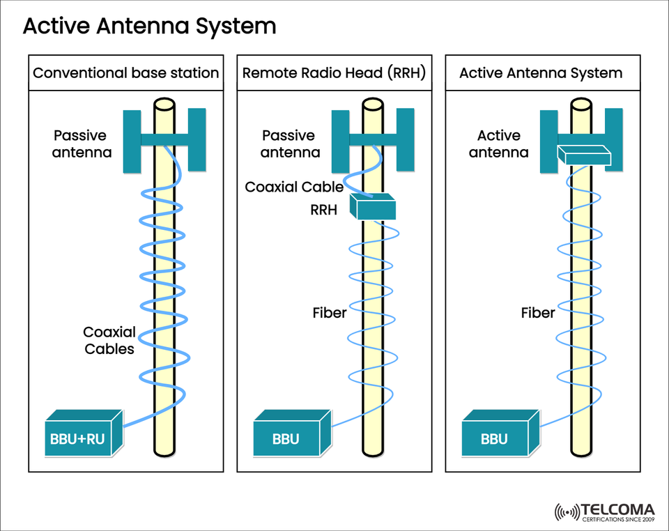
The image above from Telcoma illustrates the journey from traditional Base Stations to Remote Radio Head (RRH) setups, and ultimately to Active Antenna Systems, highlighting how each evolution leads to greater integration, efficiency, and performance.
A Look at Base Station Design Evolution
a. Conventional Base Station
Historically, base stations were made up of:
A Baseband Unit (BBU) for digital processing,
A Radio Unit (RU) linked via coaxial cables to the passive antenna.
This setup led to significant signal losses because of the long coaxial runs between the BBU/RU and the antenna. As analog signals traveled through the cables, they experienced attenuation, particularly at higher frequencies.
b. Remote Radio Head (RRH) Architecture
To address the issue of cable losses, telecom engineers adopted the RRH (Remote Radio Head) model:
The RRH is positioned close to the antenna, converting digital signals from the BBU (connected via fiber) into RF signals.
This design minimizes analog signal loss since the coaxial cable run between the RRH and antenna is much shorter.
Still, the antenna remains passive, which means it lacks active amplification or beamforming capabilities.
c. Active Antenna System (AAS)
The Active Antenna System combines the antenna elements and radio transceivers within a single housing. This allows the AAS to generate, amplify, and steer RF beams directly, enabling real-time beamforming and massive MIMO operations, both essential for 5G.
Diagram Breakdown
The uploaded image summarizes these architectures effectively:
Architecture Antenna Type Cables Used Key Components Signal Path Conventional Base Station Passive Coaxial BBU + RUBBU → RU → Coax → Antenna RRH System Passive Coaxial + Fiber BBU + RRHBBU → Fiber → RRH → Coax → Antenna Active Antenna System (AAS)Active Fiber BBU + Active Antenna BBU → Fiber → Active Antenna
Visual Summary:
Left (Conventional Base Station): Long coaxial cables connect the baseband and radio units to a passive antenna, resulting in high losses and limited beam control.
Middle (RRH): Fiber replaces coax between the BBU and RRH, cutting losses and allowing for remote setups, though the antenna remains passive.
Right (AAS): The active antenna incorporates transceiver electronics within the antenna itself, connecting directly to the BBU via fiber to support advanced features like digital beamforming.
What Is an Active Antenna System (AAS)?
An Active Antenna System merges:
Antenna array elements, and
Active components like Power Amplifiers (PA), Low Noise Amplifiers (LNA), and Transceivers (TRX).
This combination allows for signal generation, amplification, and beam steering right at the antenna.
In an AAS, each antenna element usually has its own RF chain, enabling independent control of phase and amplitude for beamforming.
- Main Components of Active Antenna Systems
- Active Antenna Array
Contains multiple antenna elements arranged in a planar array (2D).
Supports Massive MIMO (64T64R or higher).
Allows for 3D beamforming in both azimuth and elevation.
- Transceiver Modules
Transform digital signals from the baseband into RF and back.
Integrated directly into the antenna module.
- Beamforming Processor
Manages the phase and amplitude of signals at each element.
Can dynamically adjust beam directions toward user equipment (UE).
- Fiber Interface
Utilizes fiber connections between the AAS and BBU instead of coaxial cables.
Supports CPRI/eCPRI or Ethernet-based fronthaul for rapid data transfer.
How Active Antenna Systems Operate
Step 1:
The Baseband Unit (BBU) processes user data and produces baseband I/Q signals.
Step 2:
These signals are sent over optical fiber to the AAS using digital protocols (like eCPRI).
Step 3:
The AAS converts these digital baseband signals into RF signals, amplifies them, and distributes them to each antenna element.
Step 4:
The beamforming unit adjusts the phase and amplitude for each element, creating highly directional beams that follow users in real-time.
This real-time beam control helps networks focus energy where it’s needed, boosting spectral efficiency and cutting down on interference.
Advantages of Active Antenna Systems
a. Beamforming and Beam Steering
Supports dynamic beam steering to target users accurately.
Cuts down on interference and boosts network capacity.
b. Massive MIMO Support
Each antenna element can transmit and receive independently.
Enhances spectral efficiency with spatial multiplexing.
c. Reduced Cable Loss
Fiber replaces coaxial cables, lowering analog losses and improving energy efficiency.
d. Compact Integration
Combines radio and antenna in one unit, making installation and maintenance easier.
e. Better Energy Efficiency
Amplifying RF directly at the antenna reduces power wastage.
f. Enhanced Coverage and Capacity
Real-time adjustable beam control ensures consistent signal strength, even in crowded urban settings.
Tech Comparison: Passive vs Active Antenna Systems
Feature Passive Antenna System Active Antenna System (AAS)Integration Separate radio and antenna Integrated radio and antenna Beamforming Not supported Fully supported Cable Type Coaxial Fiber Losses High Low Maintenance Complex (more external units)Simplified MIMO Capability Limited Massive MIMO ready Deployment Cost Moderate Higher initial cost, lower long-term cost
- The Role of AAS in 5G Networks
The Active Antenna System serves as the backbone for 5G’s massive MIMO and beamforming capabilities.
a. Massive MIMO Integration
5G base stations utilize AAS with arrays of 64, 128, or more elements to serve multiple users on the same frequency at the same time.
b. Dynamic Beam Management
AAS allows for real-time adjustments of beam width, direction, and power, enhancing user experience based on mobility and channel conditions.
c. 3D Beamforming
Unlike older systems, AAS can create and direct beams in both azimuth and elevation, which is crucial for densely populated urban areas and multi-story buildings.
d. Edge Performance
AAS improves signal coverage at the edges of cells by dynamically directing beams where they’re needed most.
e. Scalability
Modular AAS designs can be adjusted for various deployment scenarios—macro sites, small cells, or mmWave systems.
Challenges and Considerations
Even with its benefits, implementing AAS has its hurdles:
Thermal Management: Integrated radios generate heat; effective cooling solutions are necessary.
Cost and Complexity: Initial investment is higher, and calibration can be complicated.
Weight and Wind Load: Integrated units tend to be heavier, affecting tower design.
Maintenance: Swapping out individual components (like amplifiers) can be trickier.
Still, the long-term gains—in efficiency, performance, and scalability—position AAS as the preferred architecture for modern 5G networks.
Final Thoughts
The Active Antenna System (AAS) signifies a major advancement in wireless communication infrastructure. By merging antenna and radio functionalities, it facilitates beamforming, massive MIMO, and energy efficiency—all essential for realizing 5G’s vision of incredibly fast, reliable connectivity.
From traditional coaxial-based base stations to fiber-connected active antennas, this progression reflects the telecom industry’s ongoing push for smarter, more adaptive, and high-performance networks.
In short, AAS isn’t just an upgrade—it’s the cornerstone for the intelligent, connected future of wireless communication, paving the way for 6G-ready smart networks and autonomous beam management systems.