
How OTN Maps Client Payload: Understanding Optical Transport Network Layering and Mapping

Understanding How OTN Maps Client Payloads: A Technical Overview
In today’s high-capacity transport networks, it’s essential to efficiently transmit a range of client signals using standardized methods. Optical Transport Network (OTN), which is standardized under ITU-T G.709, offers a solid digital wrapper that encapsulates various client payloads—like Ethernet, IP/MPLS, and Fibre Channel—into a single optical framework.
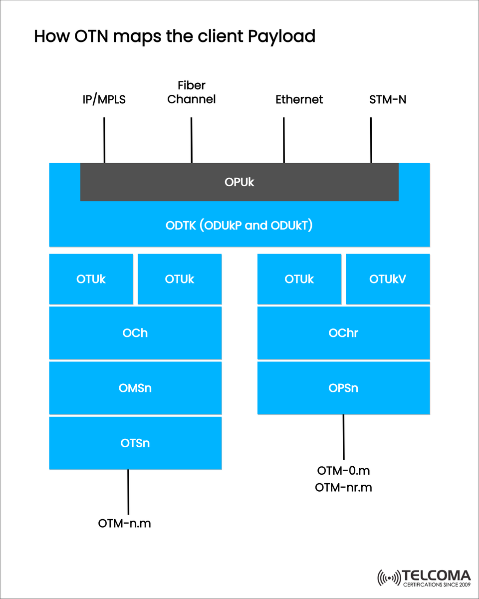
The diagram I’ve shared, titled “How OTN Maps the Client Payload”, visually breaks down how OTN achieves this mapping through a structured hierarchy of digital containers and transport layers. In this article, we’ll take a closer look at each layer and see how OTN facilitates seamless transport, multiplexing, and management of different client signals.
An Introduction to OTN: The Digital Wrapper
OTN functions as a transport layer protocol tailored for optical networks, offering features like:
Transparent client data transmission
Error checking and performance monitoring
Management signaling and synchronization
Efficient multiplexing for various data rates
Basically, OTN defines a digital wrapper that wraps client signals into Optical Data Units (ODUs) before they are sent through optical channels.
A Look at the OTN Hierarchy
The OTN hierarchy is made up of several layers that dictate how data is organized and transmitted over optical fiber. Here are the main layers:
Layer Description
OPUk (Optical Payload Unit): Encapsulates client payloads like Ethernet or IP/MPLS.
ODUk (Optical Data Unit): Adds management and multiplexing overhead to OPUk.
OTUk (Optical Transport Unit): Provides frame alignment and FEC for optical transmission.
OCh (Optical Channel): Represents the optical wavelength that carries the OTUk.
OMSn (Optical Multiplex Section): Combines multiple optical channels.
OTSn (Optical Transmission Section): Indicates the physical layer for optical fiber transmission.
Each layer builds on the one below it—similar to the stacking of OSI layers in networking—ensuring flexibility and modularity suitable for various technologies.
Mapping Client Signals into OTN
The diagram shows different client types—IP/MPLS, Fibre Channel, Ethernet, and STM-N (Synchronous Transport Module)—being mapped into the OPUk layer.
Step 1: Inserting Client Signals (OPUk Layer)
Client signals are first mapped into Optical Payload Units (OPUk).
Ethernet frames utilize GFP (Generic Framing Procedure) for mapping.
Fibre Channel and IP/MPLS are adapted through specific encapsulation methods outlined in ITU-T G.709.
STM-N (SDH/SONET) signals are mapped directly with minimal changes.
Key Function: OPUk standardizes the insertion of various client data types into OTN.
Step 2: Creating ODUk (Optical Data Unit)
The Optical Data Unit (ODUk) introduces overhead for:
Path monitoring
Error detection
Performance management
In the diagram, this is depicted as ODTK (ODUkP and ODUkT)—representing ODU Payload and ODU Tributary containers.
Multiple ODUks can be combined into higher-order ODUs, like:
ODU1 → ODU2 → ODU3 → ODU4
This layered structure supports efficient bandwidth management and caters to different service rates.
Step 3: Wrapping into OTUk (Optical Transport Unit)
The OTUk layer gives the final shape for optical transport. It covers:
Frame alignment
Forward Error Correction (FEC)
Transport overhead for section monitoring
FEC enhances transmission quality by identifying and correcting bit errors due to optical issues.
The diagram illustrates multiple OTUk layers feeding into optical channel layers, forming the foundation of the OTN transport structure.
The Optical Channel (OCh) Layer
Once the OTUk frames are ready, they get assigned to specific optical channels (OCh). Each OCh corresponds to a unique wavelength (λ) in the optical spectrum—this is where WDM (Wavelength Division Multiplexing) comes into play.
You can have multiple OChs existing on a single fiber.
Each OCh carries its own OTUk stream independently.
This separation allows service providers to handle various client types simultaneously over shared infrastructure.
OMS and OTS Layers: The Physical Transport Foundation
Beneath the OCh layer, there are two crucial layers:
OMSn (Optical Multiplex Section): Groups several OChs for transport between optical amplifiers or multiplexers, managing signal quality and optical power balancing.
OTSn (Optical Transmission Section): Represents the physical transmission medium (optical fiber), which includes the physical interfaces, amplifiers, and other optical components that carry the signal from start to finish.
The diagram also features OTM-n.m, which stands for Optical Transmission Module, detailing specific setups for optical multiplexing and demultiplexing across fiber sections.
Summary Table: OTN Mapping Layers
OTN Layer Abbreviation Function Example Technology Optical Payload Unit OPUk Maps client signals Ethernet, IP/MPLS Optical Data Unit ODUk Adds path overheadODU1–ODU4Optical Transport Unit OTUk Adds frame alignment and FECOTU2, OTU4Optical Channel OCh Represents single wavelengthλ1, λ2, λ3...Optical Multiplex Section OMSn Groups channels DWDM system Optical Transmission Section OTSn Physical fiber layer Optical fiber
Why OTN Boosts Networking Efficiency
OTN offers several advantages that make it a must-have for modern telecom infrastructure:
Support for Multiple Clients: Ethernet, IP/MPLS, Fibre Channel, and SDH can all run together.
Error Monitoring: The ODU and OTU layers ensure strong performance monitoring.
Flexible Bandwidth: ODUflex and multiplexing let OTN provide scalable bandwidth options.
Increased Resilience: Features like FEC and OAM (Operations, Administration, and Maintenance) add robustness.
Interoperability: Standards assure compatibility across various equipment vendors.
Real-World Applications
Data Center Interconnect (DCI): OTN supports high-speed interconnections between data centers using Ethernet-over-OTN mappings.
5G Backhaul Transport: Meets the high bandwidth and low latency needs of 5G networks.
Metro and Core Networks: Unifies transport for different client signals, simplifying network architecture.
Enterprise WANs: Guarantees secure, error-protected data transmission for critical applications.
Grasping OTN Multiplexing and ODU Flex
In today’s OTN deployments, ODU flex is often used as a flexible data container that can adjust to varying client bandwidths (like 10G Ethernet, 25G, 100G).
This ensures:
Efficient capacity utilization
Dynamic bandwidth allocation support
Smooth integration with packet-based services
Conclusion
The Optical Transport Network (OTN) delivers a unified, dependable, and efficient framework for sending different client payloads over optical fiber. Each layer—from OPUk to OTSn—plays a vital role in maintaining signal integrity, scalability, and manageability as illustrated in the diagram.
By standardizing how signals are mapped and multiplexed, OTN serves as a bridge between packet-based and optical transport technologies, making it fundamental to modern telecom and data center networks.