
Understanding Radiated and Conducted Reference Points for BS Type 1-O and BS Type 2-O in 5G Networks

Understanding Radiated and Conducted Reference Points for BS Type 1-O and BS Type 2-O
As 5G networks continue to develop, base station (BS) architectures have become much more complex. The 3GPP standards categorize base stations into several types to outline their hardware configurations and testing interfaces. Among these, BS Type 1-O and BS Type 2-O are key for grasping how radiated and conducted reference points are handled during Over-the-Air (OTA) testing and RF design.
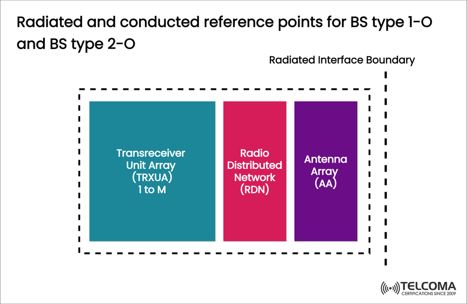
The diagram provided gives a visual representation of the reference point structure for these types of base stations. It highlights three main components — the Trans receiver Unit Array (TRXUA), the Radio Distributed Network (RDN), and the Antenna Array (AA) — all within a radiated interface boundary. This setup outlines how signals are generated, processed, and transmitted in modern 5G systems.
- Background: Why Reference Points Matter in 5G Base Stations
In previous mobile generations (think 2G, 3G, or early 4G), base stations had clear conductive interfaces that made testing RF performance straightforward via cables. But with the advent of Massive MIMO and beamforming, 5G base stations are leaning heavily on integrated active antenna systems (AAS).
These systems combine digital, RF, and antenna components into compact units, making conducted testing less feasible.
To tackle this, 3GPP introduced radiated and conducted reference points to clarify where measurements should be taken:
Conducted reference points: These are for wired measurements within the system (electrical domain).
Radiated reference points: These are for OTA measurements taken at the antenna’s radiating surface (electromagnetic domain).
BS Type 1-O and BS Type 2-O mainly focus on radiated reference points due to their fully integrated architectures.
Overview of BS Type Classifications
In the 5G ecosystem, base stations fall under the 3GPP classification as follows:
Base Station Type | Description | Measurement Approach
Type 1-C / 1-H | Conducted and hybrid systems | Conducted + Radiated
Type 1-O / 2-O | Fully integrated or Over-the-Air systems | Radiated only
For both BS Type 1-O and BS Type 2-O, there’s no available conducted interface between the transceiver and antenna, meaning all RF performance assessments (like EIRP, TRP, and sensitivity) are evaluated radiatively.
Understanding the Diagram: BS Type 1-O and 2-O Architecture
The uploaded image shows the internal signal flow and boundary definition for BS Type 1-O and 2-O. It consists of three closely integrated functional blocks:
Trans receiver Unit Array (TRXUA)
Radio Distributed Network (RDN)
Antenna Array (AA)
These parts are all contained within a radiated interface boundary, indicating that the only accessible reference point is radiative, rather than conducted.
- Trans receiver Unit Array (TRXUA)
The Trans receiver Unit Array (TRXUA) is responsible for signal transmission and reception at both the baseband and RF levels. It manages digital modulation, up/down conversion, and beamforming control.
Key Functions:
Converts baseband I/Q signals into RF signals for transmission.
Implements digital pre-distortion (DPD) and power control.
Supports multi-channel operation with scalable architecture (1 to M transceivers).
Works directly with the Radio Distributed Network (RDN) for signal distribution.
In BS Type 1-O and 2-O, the TRXUA is an embedded system — meaning it can’t be accessed for external conducted testing.
Radio Distributed Network (RDN)
The Radio Distributed Network (RDN) acts as the link between the TRXUA and the antenna array. It ensures that RF signals reach the right antenna elements while keeping synchronization, amplitude, and phase alignment intact.
Core Responsibilities:
Distributes RF energy from TRXUA to multiple antenna elements.
Handles amplification, filtering, and phase alignment.
Guarantees coherent transmission and reception for beamforming.
Manages temperature and calibration compensation for stable RF output.
The RDN is housed alongside the TRXUA and AA, forming a composite active antenna system.
Antenna Array (AA)
The Antenna Array (AA) is the last stage that transforms electrical RF signals into electromagnetic waves. For 5G NR, this array generally supports Massive MIMO and dual-polarized antenna elements.
Functions of the Antenna Array:
Radiates RF energy into free space according to beamforming vectors.
Supports spatial multiplexing for multiple users and beams.
Determines beam direction, gain, and coverage area.
Establishes the radiated interface boundary, where measurements take place.
All performance validation, including Total Radiated Power (TRP), EIRP, and beam patterns, occurs at this boundary.
- Radiated Interface Boundary Explained
In the diagram, the Radiated Interface Boundary (marked with a dashed box) contains the TRXUA, RDN, and AA. This shows that the entire system is seen as a single radiating entity.
Key Characteristics:
There are no conducted connectors available for measurement.
All testing needs to happen Over-the-Air (OTA).
The reference point for compliance testing is the electromagnetic field emitted from the antenna surface.
This design is typical for fully integrated 5G base stations, especially those utilized in small cells, mmWave systems, and Massive MIMO arrays.
- Distinguishing BS Type 1-O and BS Type 2-O
Even though both types are fully integrated and rely on radiative testing, they vary in their deployment scenarios and functional partitioning.
Aspect BS Type 1-OBS Type 2-OArchitectureFully integrated gNB (base station)Centralized or distributed gNB function Control Unit Combines control and user plane functions Possibly separates control and user planes Interface Type Radiated (OTA only)Radiated (OTA only)Testing Focus Transmit/receive radiated power, beam characteristics Radiated performance, synchronization, EIRP Deployment Example Urban macro/micro base stations Distributed or small cell 5G nodes
In both situations, the radiated reference point serves as the primary interface for RF validation.
Conducted vs. Radiated Reference Points
Measurement Type Definition Applicable BS Type Conducted Reference Point Electrical interface for RF testing (via cable)BS Type 1-C, 1-HRadiated Reference Point OTA measurement interface for EIRP/TRPBS Type 1-O, 2-O
This table helps clarify why 5G testing has moved from conducted methods (like older systems) to OTA testing, particularly for active antenna systems (AAS).
Advantages of the Integrated (Radiated-Only) Design
BS Type 1-O and 2-O designs come with several practical and technical perks:
Less cable loss: No long RF cables between units.
Greater integration: Compact form factor and efficient cooling.
Better beamforming precision: Close synchronization between TRXUA and AA.
Stabilized calibration: Factory-calibrated composite units keep consistency.
Easier deployment: Fewer external interfaces and connectors.
That said, this also brings testing challenges, as engineers must depend solely on OTA measurement systems to validate performance.
Conclusion
The architectures of BS Type 1-O and BS Type 2-O signify an important step in the evolution of 5G, showcasing fully integrated, radiated-only systems. By enclosing the Trans receiver Unit Array (TRXUA), Radio Distributed Network (RDN), and Antenna Array (AA) within a single radiated interface boundary, these designs eliminate traditional conducted interfaces, enhancing deployment efficiency while maximizing effectiveness.
The diagram clearly illustrates how this integration simplifies the signal flow and establishes a singular radiated reference point for performance validation. As 5G continues to expand — and research into 6G advances — grasping these architectures is crucial for professionals aiming to excel in network design, compliance, and real-world execution.