
Understanding the 5G Standalone Access Registration Procedure: Step-by-Step Explained

5G Standalone Access Registration Procedure: A Technical Overview
As 5G networks transition from Non-Standalone (NSA) to Standalone (SA) architecture, the registration process becomes vital for creating a direct connection between the User Equipment (UE) and the 5G Core (5GC) without relying on LTE.
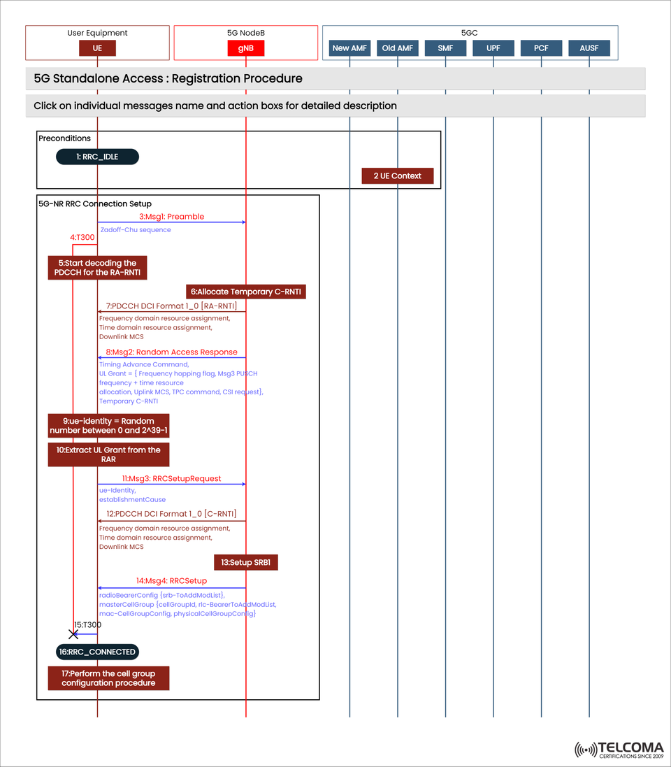
The image provided by Telcoma shows the 5G Standalone Access: Registration Procedure, which highlights the signaling interactions between UE, gNB (5G NodeB), and components of the 5GC—like AMF (Access and Mobility Management Function), SMF (Session Management Function), UPF (User Plane Function), PCF (Policy Control Function), and AUSF (Authentication Server Function).
Introduction to 5G Standalone Architecture
Unlike 5G NSA, where LTE anchors control-plane functions, 5G Standalone (SA) fully utilizes the 5G Core (5GC).
Key components involved are:
UE (User Equipment): The device that starts the network access.
gNB (5G NodeB): Manages radio transmission and oversees the RRC/RLC/MAC layers.
5GC Components:
AMF: Handles access, registration, and mobility.
SMF: Manages session functions and allocates IP addresses.
UPF: Directs user-plane traffic.
PCF: Implements policies and manages Quality of Service.
AUSF: Authenticates the UE.
This complete setup allows for ultra-low latency, dynamic slicing, and independent network operation, which are crucial for massive IoT and URLLC use cases.
Preconditions: UE in RRC_IDLE
The registration process kicks off with the UE in the RRC_IDLE state—disconnected but still synced with the cell.
At this point, the UE keeps an eye on system information blocks (SIBs) and cell parameters that the gNB broadcasts. When it’s ready to access the network (for registration or data transfer), it starts the Random Access Procedure (RACH).
The Random Access Procedure (RACH): Initial Access to the gNB
The Random Access Channel (RACH) process is how the UE connects with the gNB and requests radio resources.
Step-by-Step Breakdown:
Step Message Description
Msg1: Preamble (Zadoff-Chu Sequence)
The UE sends a random preamble sequence to the gNB to initiate access.
Msg2: Random Access Response (RAR)
gNB responds with timing advance, temporary C-RNTI, and UL grant.
Msg3: RRCSetupRequest
UE requests an RRC connection, including a unique identifier.
Msg4: RRCSetup
gNB approves the request and sends configuration parameters.
Let’s examine each of these in the context of the image:
3.1 Msg1: Preamble Transmission
The UE sends a preamble using a Zadoff-Chu sequence on the RACH, which helps the gNB detect the UE’s presence and timing offset.
3.2 Msg2: Random Access Response (RAR)
After receiving Msg1, the gNB sends Msg2 (RAR), which includes:
Timing Advance Command: Syncs UE timing with the network.
Uplink (UL) Grant: Provides uplink resources for Msg3.
Temporary C-RNTI: A temporary identifier for further communication.
The UE then decodes the PDCCH (Physical Downlink Control Channel) using the RA-RNTI and processes the RAR information from the PDSCH (Physical Downlink Shared Channel).
3.3 Msg3: RRCSetupRequest
With the uplink resources in hand, the UE sends Msg3, an RRCSetupRequest, to the gNB. This message includes:
A random UE identity (a number between 0 and 2^39-1).
An establishment reason (like an emergency or a mobile-originated data request).
This marks the start of the RRC Connection Setup procedure.
3.4 Msg4: RRC Setup
The gNB checks the request and responds with Msg4 (RRCSetup), which contains configuration details such as:
Radio Bearer Config
Master Cell Group info
Cell Group Config for control and data channels
Once the UE decodes this successfully, it moves to RRC_CONNECTED.
RRC Connection Setup Completion
After the RRC Setup is done, the UE sends RRC Setup Complete to confirm.
At this point:
The Signaling Radio Bearer (SRB1) is established.
The UE now has a C-RNTI (Cell Radio Network Temporary Identifier).
There’s a dedicated control path to the UE from the network.
The UE can now exchange NAS (Non-Access Stratum) messages with the AMF through the gNB.
NAS Registration Procedure with 5G Core
Once the RRC connection is set up, the UE starts the NAS-level registration with the 5G Core Network via the AMF.
Core Steps:
NAS Registration Request: UE → gNB → AMF.
Authentication Request/Response: AMF ↔ AUSF validates UE credentials.
Security Mode Command: AMF sets up ciphering and integrity protection.
Registration Accept: UE is now officially registered with the 5GC.
Registration Complete: UE confirms its registration.
At this point, the UE can request PDU sessions through the SMF to access data networks.
- Detailed Breakdown of Message Flow (As per Image)
Step Message / Action Purpose
UE in RRC_IDLE: Initial state before connection.
Msg1: Preamble: UE starts the random access.
T3100 Timer Starts: Wait for the RAR response.
5-6. Decode PDCCH, Allocate C-RNTI: Assigns uplink control resources.
Msg2: Random Access Response: Network assigns UL grant and timing advance.
9-10. UL Grant Extraction: UE prepares to send Msg3.
Msg3: RRC Setup Request: UE asks for connection setup.
PDCCH DCI Format 1_0 (C-RNTI): Schedules Msg4.
Setup SRB1: Control plane channel for signaling.
Msg4: RRC Setup: Network finalizes the configuration.
T300 Timer Starts: Monitors connection setup.
RRC_CONNECTED: Connection is established.
Cell Group Configuration: Completes UE setup.
This flow makes sure that synchronization, identity verification, and secure radio configuration are done before moving onto the core registration phase.
Transition from RRC_CONNECTED to Full Registration
Once the RRC connection is stable, the NAS layer kicks off the registration with the 5GC. The AMF:
Authenticates the UE via AUSF.
Sets up security and integrity protection.
Manages session management through SMF.
Finally, the UPF sets up user-plane routes, allowing data transfer.
This wraps up the 5G SA registration process, allowing the UE direct access to 5G services over the 5GC.
Advantages of 5G Standalone Access Procedure
Even though the SA mode’s registration process is pretty complex, it offers some significant benefits:
Key Advantages:
End-to-End 5G Core Integration: No need for LTE anchors.
Ultra-Low Latency: Optimized signaling with dedicated 5GC access.
Dynamic Network Slicing: Allows personalized service instances for users.
Improved Security: Native 5G authentication via AUSF/UDM.
More Efficient Mobility Management: Unified AMF-based session continuity.
These features make SA networks more scalable, efficient, and ready for the future.
Comparison: 5G NSA vs SA Registration
Feature 5G NSA 5G SA
Control Plane: Anchored on LTE EPC | Native 5G Core
Latency: Higher (due to LTE dependency) | Ultra-low
Spectrum Utilization: Partial NR usage | Full NR operation
Network Slicing: Limited | Fully supported
Deployment Complexity: Moderate | High but future-proof
Conclusion
The 5G Standalone Registration Procedure is a key part of the next generation of connectivity. It allows for direct communication between the UE and 5GC, forming the basis for AI-driven, low-latency, and service-oriented networks.
This illustrated signaling flow—from RRC connection setup to NAS registration—shows how each layer contributes to a seamless, secure, and efficient connection within the 5G ecosystem.
As operators worldwide make the shift to SA deployments, grasping these message exchanges is crucial for optimizing performance, ensuring compatibility, and preparing for the evolution to 6G.