
Understanding the Block Diagram of FSO Communication Links: Components, Operation, and Atmospheric Challenges

Understanding the Block Diagram of FSO Communication Links
As the global demand for data increases and radio frequencies get crowded, Free Space Optical (FSO) communication stands out as a fantastic option for high-speed wireless data transfer. By utilizing light waves rather than radio frequencies, FSO systems provide ultra-fast, secure, and interference-free communication through the open air or even space.
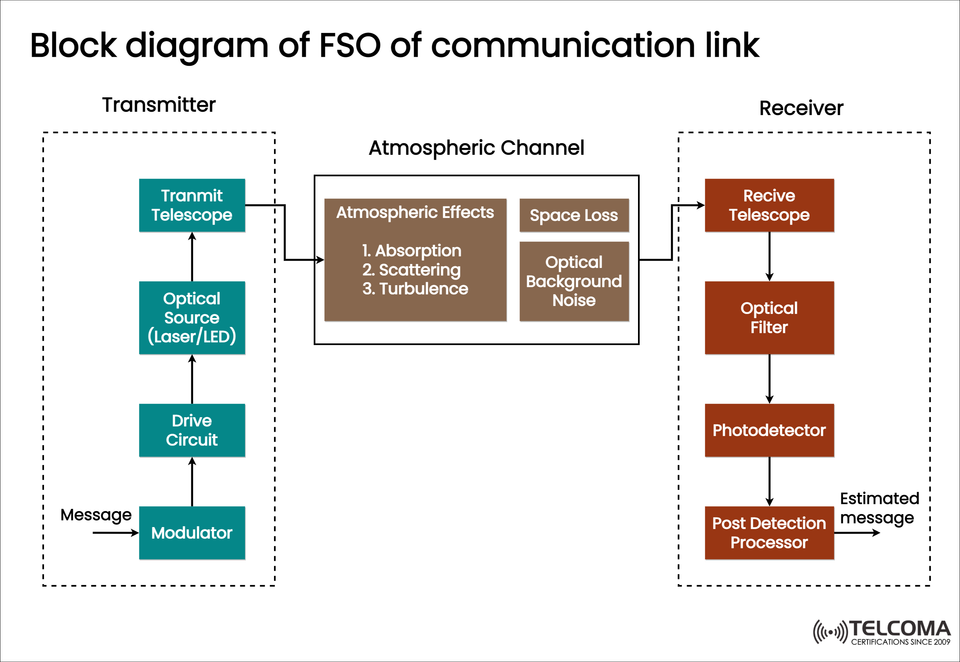
The block diagram of an FSO communication link, which you can see in the image above, highlights the three main sections of the system:
Transmitter Section
Atmospheric Channel
Receiver Section
Every block in this diagram is crucial for ensuring that data is transferred accurately over optical beams. So, let's dive into each part and see how FSO communication works from start to finish.
Introduction to FSO Communication
FSO communication sends information using modulated light beams, typically from a laser diode or LED, across free space — meaning it doesn’t require any physical medium like fiber optic cables.
It's commonly used in:
Satellite-to-satellite and satellite-to-ground connections
UAV and aircraft communication
Urban point-to-point links
5G backhaul and data center interconnects
Advantages of FSO Communication:
Gigabit speeds comparable to optical fiber.
No licensing required, as the optical spectrum is unregulated.
Highly secure, thanks to narrow beam divergence.
Quick deployment without the need for digging or cabling.
That said, FSO's performance can be affected by atmospheric conditions like fog, rain, and turbulence — issues that are clearly illustrated in the atmospheric block of the diagram.
Overview of the FSO Communication System
The FSO system is made up of three key components:
Section | Function | Key Components
Transmitter | Converts electrical data into optical signals | Modulator, Drive Circuit, Optical Source, Transmit Telescope
Atmospheric Channel | Carries optical signal through free space | Absorption, Scattering, Turbulence, Optical Noise
Receiver | Captures optical signal and recovers original message | Receive Telescope, Optical Filter, Photodetector, Post-Detection Processor
Transmitter Section: From Data to Light
The transmitter is where the magic begins, converting an electrical message into an optical beam that can travel through free space. The blocks in this section (as seen in the image) include:
a. Modulator
The modulator takes the input message signal — whether it’s digital or analog — and encodes it on an optical carrier wave.
Common modulation methods are On-Off Keying (OOK), Pulse Position Modulation (PPM), and Subcarrier Intensity Modulation (SIM).
The modulator is crucial for efficient data encoding to achieve high-speed transmission.
b. Drive Circuit
The drive circuit amplifies and conditions the modulated signal to control the optical source.
It transforms the low-power modulated input into a suitable current or voltage for laser diode or LED excitation.
It’s essential that the drive circuitry is precise so the beam remains stable and noise is kept to a minimum.
c. Optical Source (Laser/LED)
The optical source is the core of the transmitter, emitting light at specific wavelengths (usually 850 nm, 1310 nm, or 1550 nm).
Laser Diodes provide high coherence and narrow beam divergence, making them perfect for long-distance FSO connections.
LEDs are better for short-range tasks, as they have a broader beam and lower coherence.
d. Transmit Telescope
The transmit telescope collimates (narrows and aligns) the optical beam before shooting it out into free space.
This ensures the optical signal keeps its intensity and alignment over distance.
In satellite or UAV links, precision tracking and beam steering systems are built in to maintain alignment even when in motion.
Once the beam shoots out from the telescope, it travels through the atmospheric channel — the trickiest part of FSO communication.
Atmospheric Channel: The Free Space Pathway
The atmospheric channel is a dynamic and often unpredictable medium that can influence the strength and quality of the optical beam. The diagram presents three main effects: Absorption, Scattering, and Turbulence, along with Space Loss and Optical Background Noise:
a. Atmospheric Effects
Absorption:
Caused by molecules like water vapor, CO₂, and O₃ absorbing light energy.
Leads to attenuation and a drop in power of the transmitted signal.
Scattering:
Happens when particles like fog, rain, or dust deflect the optical beam.
There are two main types: Rayleigh Scattering (small particles) and Mie Scattering (large particles).
Scattering reduces signal strength and causes beam divergence.
Turbulence:
Arises from variations in air temperature and refractive index.
Leads to beam wander, scintillation, and signal fading.
b. Space Loss
This refers to the geometric spreading of the optical beam as it moves through space.
The more distance it covers, the weaker the received signal due to beam divergence.
c. Optical Background Noise
Ambient light from sources like the sun or streetlights creates optical background noise.
This noise can confuse the receiver’s ability to differentiate the signal from the background.
Mitigation Techniques
To tackle these atmospheric challenges, FSO systems use:
Adaptive optics to fix beam distortions.
Automatic tracking for stability in alignment.
Hybrid RF/FSO systems to provide backup connections during poor weather.
Error correction coding (ECC) to boost data reliability.
Receiver Section: Recovering the Message
When the optical beam finally arrives at its destination, the receiver converts it back into an electrical signal. Each block in the receiver section has a vital role in signal recovery.
a. Receive Telescope
The receive telescope gathers and focuses the incoming optical beam onto the detector.
High-gain optical lenses and alignment mechanisms are used to ensure efficient light capture, even with slight misalignment or turbulence.
b. Optical Filter
The optical filter isolates the chosen wavelength while blocking out unwanted background noise.
This significantly enhances the signal-to-noise ratio (SNR), ensuring only the necessary optical energy reaches the detector.
c. Photodetector
Converts the optical power into an electrical current that’s proportional to the intensity of the incoming beam.
Common detectors include:
PIN Photodiode – quick response, low noise.
Avalanche Photodiode (APD) – higher sensitivity with internal gain.
d. Post Detection Processor
The post detection processor amplifies, demodulates, and reconstructs the original message.
It involves digital signal processing (DSP), filtering, and error correction modules.
The end product is the estimated message, which closely matches the original input signal.
End-to-End FSO Communication Process
Here’s a summary of how the whole operation flows:
Step | Process Description
1 | Input message is modulated and encoded into an optical signal.
2 | The drive circuit powers the optical source (laser/LED).
3 | Transmit telescope directs the optical beam into free space.
4 | The beam goes through the atmosphere, facing absorption, scattering, and turbulence.
5 | The receive telescope captures the weakened optical beam.
6 | Optical filters and detectors convert light back to an electrical signal.
7 | The post detection processor reconstructs the original message.
This smooth conversion and recovery process allows FSO systems to achieve high-speed, low-latency, and secure data transmission over distances ranging from a few meters to several kilometers — or even between satellites.
Challenges and Future Prospects
Although FSO is well-established, there are still some challenges:
Weather dependency: Fog and heavy rain can greatly impact link quality.
Alignment precision: Both ends need to keep a perfect line of sight.
Limited range: Usually just a few kilometers for terrestrial links.
But with advancements in beam tracking, adaptive optics, and hybrid systems, FSO is becoming crucial for:
6G networks and inter-satellite optical links.
Smart city connectivity and urban backhaul.
Deep-space communication and autonomous aerial networks.
Conclusion: The Light-Powered Future of Communication
The block diagram of an FSO communication link clearly outlines how light-based wireless communication operates — from laser modulation to optical detection. Every component, from the transmitter to the receiver, is essential in preserving the integrity of the signal despite atmospheric hurdles.
As the demand for data continues to increase, FSO provides a strong, flexible, and scalable solution for the communication systems of the future. Whether it's connecting satellites in orbit, drones in the sky, or buildings in a smart city, FSO technology is poised to become a cornerstone of high-speed optical wireless networks in the 6G era and beyond.