
UPA vs. NUPA in 5G Antenna Arrays: Understanding Uniform and Non-Uniform Planar Arrays

UPA vs. NUPA in 5G Antenna Arrays: A Comprehensive Guide
With the worldwide spread of 5G networks, massive MIMO (Multiple Input Multiple Output) and beamforming have become foundational for current wireless communication. At the heart of these technologies are antenna arrays—specialized setups of multiple antenna elements crafted to efficiently direct radio energy.
When it comes to these setups, two types lead the way in 5G base station design: the Uniform Planar Array (UPA) and the Non-Uniform Planar Array (NUPA).
The Basics: What Are Planar Antenna Arrays?
A planar antenna array is a two-dimensional layout of individual antenna elements set along both the horizontal (x) and vertical (y) axes.
Each element plays a part in shaping the overall radiation pattern. By adjusting the amplitude and phase of the signals sent to each antenna, the array can steer beams in the intended directions, a technique called beamforming.
Uniform Planar Array (UPA): Structure and Operation
Definition:
A Uniform Planar Array (UPA) is made up of antenna elements positioned at regular, evenly spaced intervals along the x and y axes.
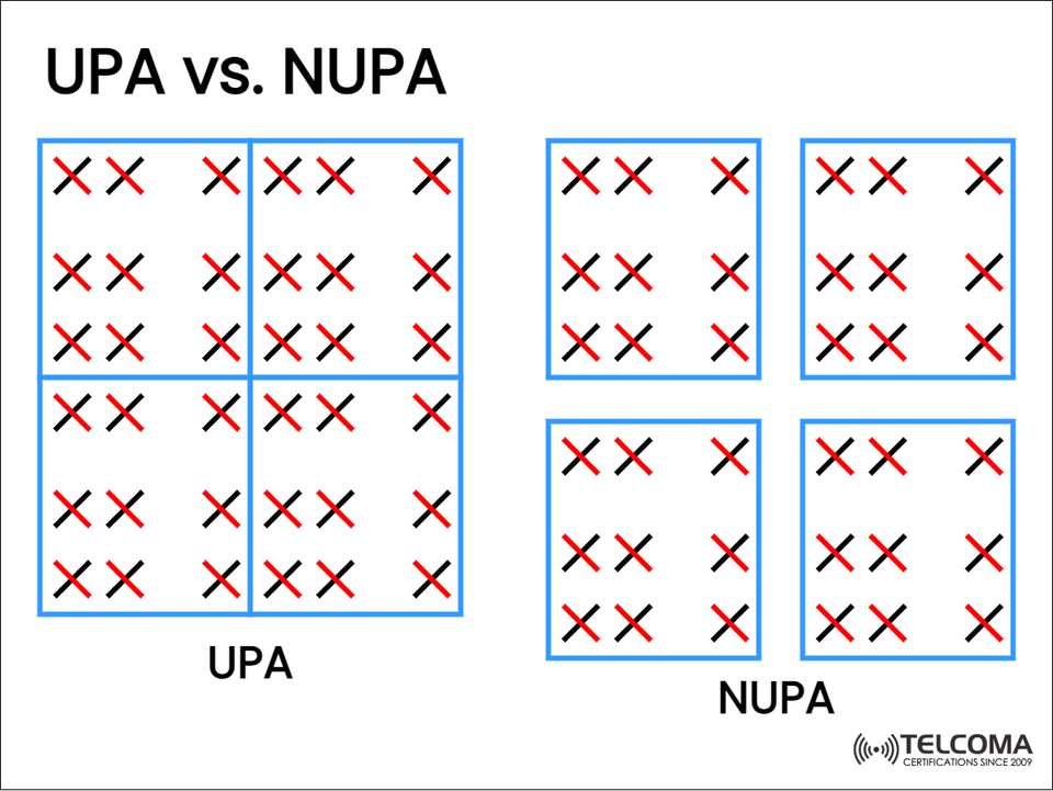
The image shows the left grid labeled UPA with:
Evenly spaced black and red “X” marks that symbolize antenna elements.
A single contiguous block divided into smaller, uniform sections.
Characteristics of UPA:
Equal spacing between elements, typically at d=λ/2 (half the wavelength).
Symmetrical layout, making array factor calculations easier.
Simpler beamforming control, with predictable phase shifts.
Ideal for dense setups where uniform coverage and consistent radiation patterns are critical.
Advantages of UPA:
✅ Simplified modeling and calibration.
✅ Consistent side-lobe levels for better interference management.
✅ High beamforming accuracy in both azimuth and elevation.
✅ Easy to integrate with digital beamforming algorithms in massive MIMO.
Applications:
Used in macro base stations for 5G NR.
Useful for fixed wireless access (FWA).
Employed in satellite and radar arrays that require precise scanning.
Non-Uniform Planar Array (NUPA): Structure and Concept
Definition:
A Non-Uniform Planar Array (NUPA), depicted on the right side of the image, includes multiple smaller subarrays or clusters of antenna elements arranged with non-uniform spacing.
Unlike a large, evenly spaced array, the NUPA layout divides the structure into several smaller planar sections, each positioned independently.
Characteristics of NUPA:
Irregular inter-element spacing between subarrays.
Can follow optimized or random spacing to minimize mutual coupling.
Promotes spatial diversity and custom beam patterns.
Ideal for scenarios where physical constraints or coverage goals demand flexibility.
Advantages of NUPA:
✅ Less mutual coupling between subarrays, reducing distortion.
✅ Greater layout flexibility for non-uniform surfaces or shapes.
✅ Potential for multi-beam generation and spatial diversity.
✅ Enhanced robustness against multipath fading in complex settings.
Applications:
Suitable for compact small-cell or indoor 5G setups.
Appears in mmWave beamforming systems with size constraints.
Employed in UAVs, automotive radar, and mobile platforms where planar uniformity is challenging.
Mathematical Foundation: UPA vs. NUPA Array Factors
Uniform Planar Array:
For an M×N UPA spaced by dx and dy:
AFUPA(θ,ϕ)=∑m=0M−1∑n=0N−1wmnejk(mdxsinθcosϕ+ndysinθsinϕ)
Where:
AFUPA = Array Factor
wmn = Complex weight of element (m,n)
k=2π/λ = Wave number
This uniform structure simplifies to well-defined main lobes and side lobes, allowing accurate beam steering.
Non-Uniform Planar Array:
In NUPA, element positions (xm,yn) are not uniform:
AFNUPA(θ,ϕ)=∑m=0M−1∑n=0N−1wmnejk(xmsinθcosϕ+ynsinθsinϕ)
This results in customized beam shapes, but typically requires optimization algorithms (like genetic algorithms or convex optimization) to minimize side lobes or grating lobes.
5G and Massive MIMO Implications
a. Beamforming Performance
UPA: Works best for narrow, high-gain beams—essential for 5G macro cells and mmWave connections.
NUPA: Offers multi-beam and adaptive coverage, enhancing spectral efficiency in crowded areas.
b. Array Calibration
UPA: Easier to calibrate because of its consistent spacing and symmetry among elements.
NUPA: Needs more advanced calibration and alignment techniques.
c. Mutual Coupling and Interference
UPA: Elements placed closely can lead to strong coupling, distorting how the radiation patterns look.
NUPA: More spaced-out or irregular arrangements reduce coupling effects, improving isolation between subarrays.
d. Implementation Cost
UPA: Simple, standardized design, but demands tight manufacturing tolerances.
NUPA: More adaptable physically but requires complex digital beamforming and calibration systems.
Why 5G Designers Choose Between UPA and NUPA
The choice between UPA and NUPA hinges on several system design factors:
Frequency Band:
UPA is great for Sub-6 GHz and early mmWave bands.
NUPA is preferable for higher mmWave or THz systems needing flexible designs.
Coverage vs. Capacity:
UPA offers uniform coverage and strong beamforming gain.
NUPA accommodates multi-user beams for greater capacity.
Deployment Environment:
UPA works well for macro and rooftop installations.
NUPA is ideal for compact or irregular setups, like vehicles or drones.
Manufacturing Constraints:
NUPA designs support modular production using pre-fabricated subarrays.
Practical Example: 64T64R 5G Antenna Panels
In real-world 5G NR deployments:
UPA-based panels usually have 8×8 or 16×16 arrays for massive MIMO systems.
NUPA configurations are found in Active Antenna Systems (AAS) or hybrid beamforming modules, where smaller panels (subarrays) work together.
For example:
A 64T64R UPA base station offers a single wide beamforming panel.
A 64T64R NUPA system splits elements into four 16T16R subarrays, managing independent beams—providing sector flexibility and power efficiency.
Future of Planar Arrays in 6G
As we approach 6G, the lines between UPA and NUPA will continue to blur:
Reconfigurable Intelligent Surfaces (RIS) will make use of non-uniform reflective element placement (similar to NUPA).
Hybrid analog-digital beamforming will combine the precision of UPA with the flexibility of NUPA.
AI-driven optimization will dynamically modify element spacing and phase alignment in real-time.
This progression aims to deliver ultra-precise spatial control, energy efficiency, and beam agility for the next generation of networks.
Conclusion
The difference between UPA and NUPA illustrates two design philosophies in antenna engineering:
UPA focuses on uniformity, simplicity, and predictable performance—perfect for high-precision, large-scale 5G applications.
NUPA highlights flexibility, reduced coupling, and adaptive beamforming, making it fit for intricate or challenging environments.
Both types are crucial in modern communication systems. As we transition from 5G to 6G, hybrid designs that blend the strengths of uniform precision and non-uniform adaptability will shape the future of antenna technology.